
Apparatus and method for augmenting sight

a technology of eye augmenting and eyeglasses, applied in the field of eye augmenting, can solve the problems of no amd cure, significant loss of vision, and death of the eye cells necessary for vision, and achieve the effect of improving the visual acuity of the patient and improving the visual function

Inactive Publication Date: 2012-03-13
ESIGHT CORP
View PDF44 Cites 58 Cited by
  • Summary
  • Abstract
  • Description
  • Claims
  • Application Information

AI Technical Summary

Benefits of technology

The invention is about a method and apparatus for improving sight for individuals with visual impairments. The method involves capturing an image of a scene and transmitting it to a processor, which modifies the image by adding appropriate modifications such as magnification, remapping, minification, edge enhancement, and so on. The modified image is then displayed on a display device worn by the individual. The apparatus includes an image capture device attached to glasses or a camera, a display, and a processor for mapping the image to the display in a way that avoids areas of retinal damage or other visual defects. The technical effects of this invention include improved visual function and acuity for individuals with retinal degeneration.

Problems solved by technology

In macular degeneration, which begins with the deposit of druesends in layers beneath the photoreceptors, the degenerative process affects mostly the macula and results in death of cells necessary for vision.
At this time there is no cure for AMD.
Other diseases (such as, but not only, diabetic retinopathy, glaucoma, macular edema, and optic nerve atrophy) can also result in significant losses in vision, sometimes macular, sometimes peripheral, to this region of high quality vision.
What these vision losses have in common is the loss in quality of life due to the reduced quality of vision.
These devices tend to be big, bulky, limited in their application, and not appropriate for non-military or paramilitary uses.

Method used


Image

  • Apparatus and method for augmenting sight
  • Apparatus and method for augmenting sight
  • Apparatus and method for augmenting sight

Examples


Embodiment Construction

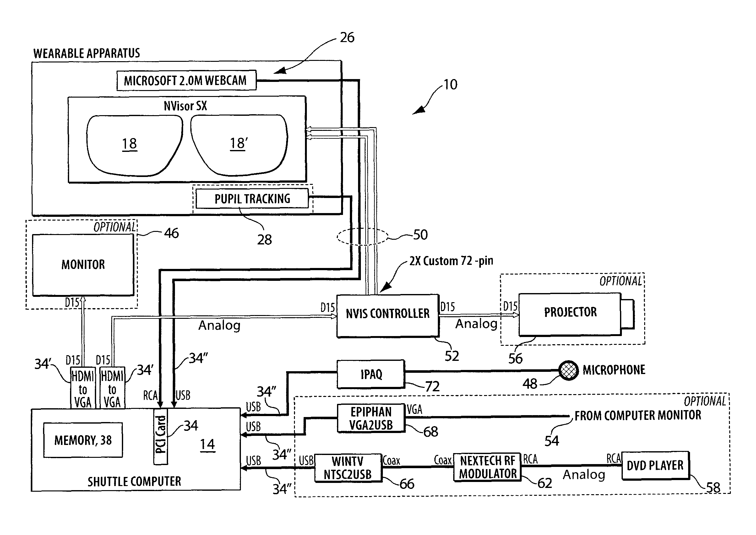
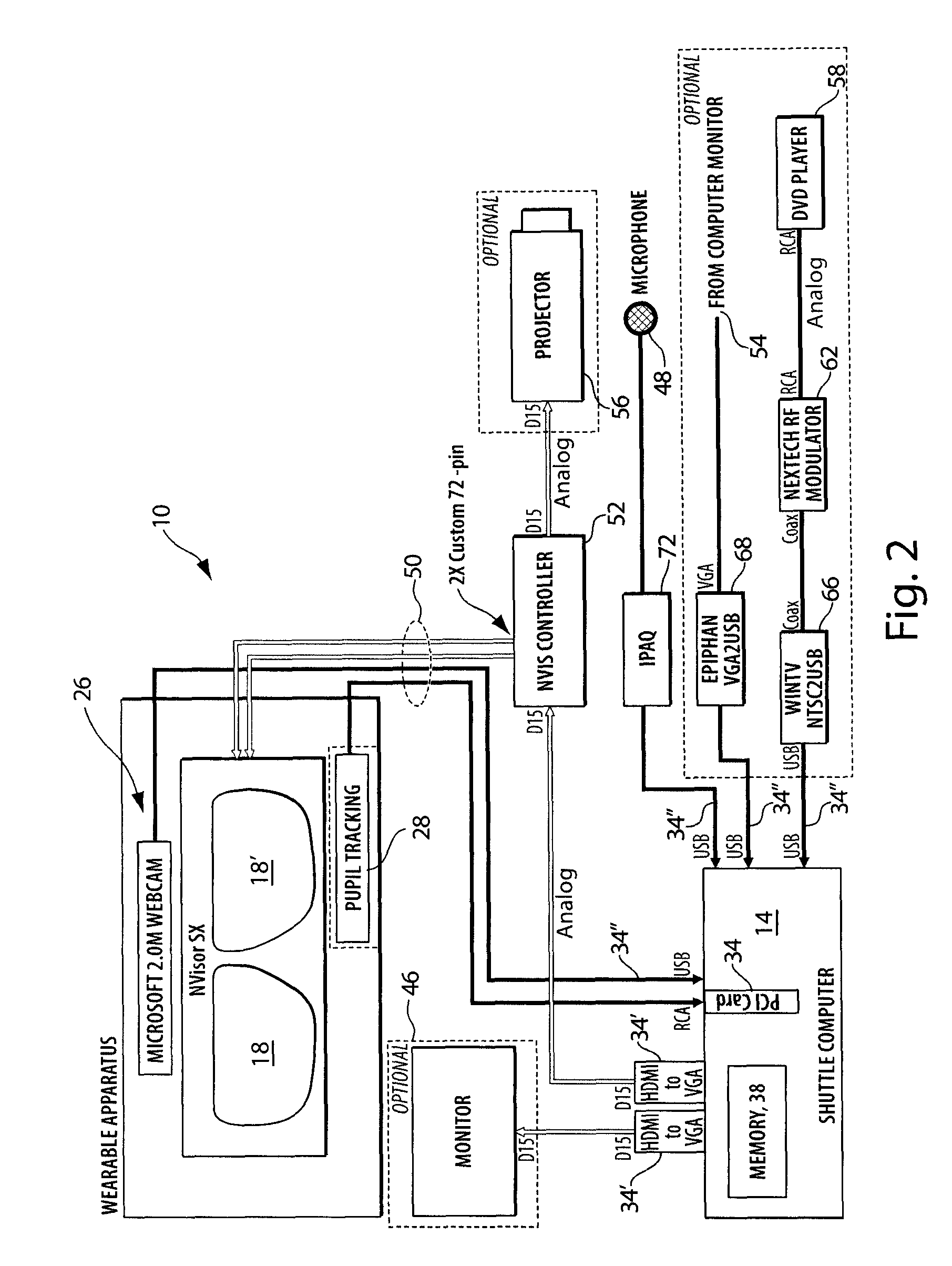
[0024]In brief overview and referring to FIG. 2, the system for augmenting sight in one embodiment includes a pair of eyeglass frames 10 or headmounted display, such as an Nvisor SX, by NVIS (Reston, Va.), and a processor 14. In one embodiment, the processor 14 is a general purpose computer, such as made by Shuttle Computer Group (City of Industry, Calif.). The eyeglass frames 10 are the typical eyeglass frames generally available and used today with transparent lenses. In this embodiment, the transparent lenses have been replaced with one or two display screens 18, 18′ (generally 18). Attached to the frames 10 are one or more image capture devices 26, such as a camera. In one embodiment, the image capture device is a Microsoft 2.0M Webcam (Redmond, Wash.). Optionally, one or more eye or pupil tracking sensors 28 and associated electronics are also attached to the frames 10. The electronics provide for image capture by the image capture device 26 and transmission to the processor 14...


PUM


Abstract

A method of augmenting sight in an individual. The method comprises obtaining an image of a scene using a camera carried by the individual; transmitting the obtained image to a processor carried by the individual; selecting an image modification to be applied to the image by the processor; operating upon the image to create a modified image using either analog or digital imaging techniques, and displaying the modified image on a display device worn by the individual. The invention also relates to an apparatus augmenting sight in an individual. The apparatus comprises a camera, carried by the individual, for obtaining an image of a scene viewed by the individual; a display carried by the individual; an image modification input device carried by the individual; and a processor, carried by the individual. The processor modifies the image and displays the modified image on the display carried by the individual.

Description

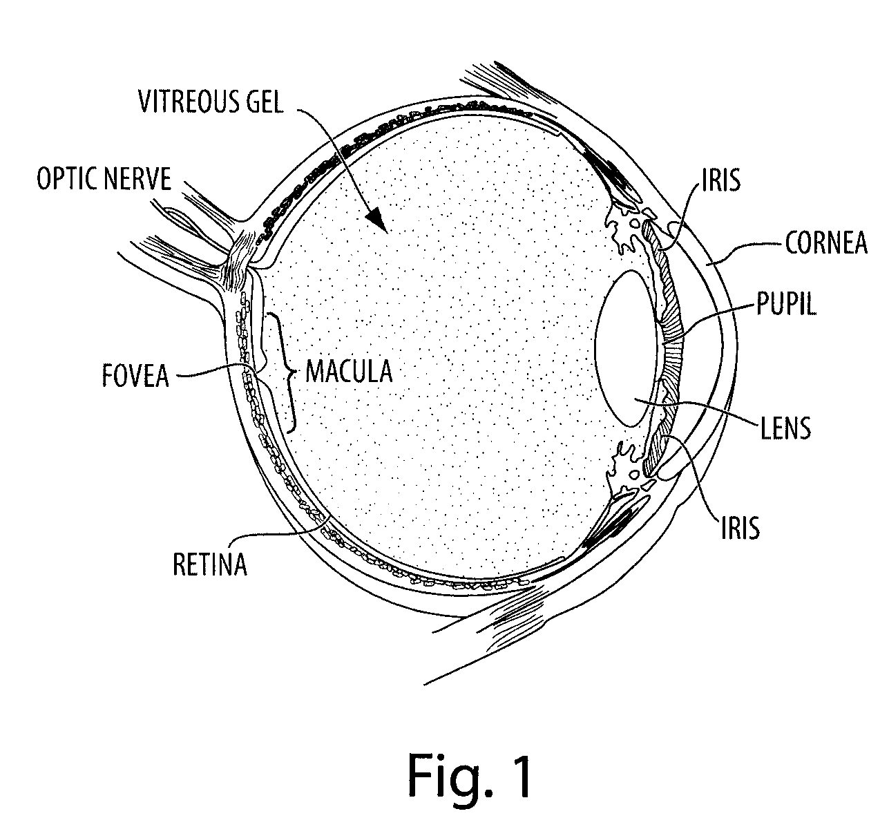
CROSS REFERENCE TO RELATED APPLICATIONS[0001]This application claims priority to U.S. provisional application 60 / 921,468 filed Apr. 2, 2007 and assigned to the assignee of the present application. The provisional application is herein incorporated in its entirety by reference.FIELD OF THE INVENTION[0002]The invention relates generally to the field of vision care and more specifically to the field of augmenting sight.BACKGROUND OF THE INVENTION[0003]There are conditions under which even individuals with 20 / 20 vision need sight augmentation. Such conditions may be brought on by, for example, low light levels, low or no color differentiation between objects in the visual field, or the small size of the object viewed. Individuals with less than optimal vision or with other visual defects, such as retinopathies, also need augmentation to correct for their visual defects.[0004]FIG. 1 is a schematic diagram of the eye. A portion of the retina responsible for fine detail vision is the macul...

Claims


Application Information

Patent Timeline
Patent Type & Authority Patents(United States)
IPC IPC(8): G06K9/40G06K9/00G16H20/30G16H30/40
CPCG02B27/017G06Q50/22G09B21/008G06T19/006G02B2027/0112G02B2027/0118G02B2027/0138G02B2027/014G16H30/40G16H20/30G02C11/10G02C2202/10
Inventor LEWIS, CONRAD W.MATHERS, DANIEL R.HILKES, ROBERT G.MUNGER, REJEAN J. Y. B.COLBECK, ROGER P.
Owner ESIGHT CORP
Learn More