Optical See-Through Head Worn Display

a display and optical technology, applied in the field of head worn displays, can solve the problems of significant handicapping the wearer, limited head worn display performance, and difficult design and manufacture, and achieve the effect of high acuity

Inactive Publication Date: 2018-03-22
BELENKII MICHAEL +3
View PDF2 Cites 50 Cited by
  • Summary
  • Abstract
  • Description
  • Claims
  • Application Information

AI Technical Summary

Benefits of technology

[0013]The present invention provides an augmented reality head worn device comprising a curve combiner transparent to visible light and reflective in an selected infrared frequency range, a scanning light source defining a field of view, a holographic optical element adapted to provide pupil expansion to create an eye-box, and at least one projection system for providing high acuity at or near a center of the field of view. Embodiments of the invention include a laser scanning projector, one or more lenses, one or two holographic optical elements (HOE) and a curved combiner. The laser scanning projector provides narrow laser beams in multiple wavelengths scanned over a field of view. The narrow laser beams can be collimated and can have a beam waist. The wavelengths are preferably red, green and blue for producing color images, but the number of colors is not limited to three. The projector provides a 2D image by scanning a mirror that deflects the narrow laser beams in two dimensional directions along with the laser modulation in synchronization with image signals. In preferred embodiments the projector may provide a controlled and variable beam divergent laser beam by placing a small focusing lens in the optical path prior to the scanning mirror. The small focusing lens can be a variable focusing lens. In addition a large focusing lens may be included after the scanning mirror, or the two lenses could be replaced by a single specially designed lens. The HOE can be placed at, or in the vicinity of, a focal plane of the focusing lens or lenses. The HOE generates multiple diffracted beams that are directed to respective positions on the curved combiner. The HOE can be surface relief hologram, a grating, or volume hologram. Preferably the HOE is equipped with designated sub-areas to generate diffracted beam of each of the three wavelengths. The radius of curvature of the outer (convex) surface of the combiner is larger than the radius of curvature of the inner (concave) surfaces of the combiner y and amount equal to the thickness of the combiner, to provide an undistorted see-through image. The inner surface is preferably coated with a notch filter coating on the inner surface to reflect only the red, green and blue beams from the HOE and to transmit light at other wavelengths. The combiner also preferably includes an anti-reflection coating on the outer surface.

Problems solved by technology

The performance of current head worn displays is limited compared to the typical human visual capability.
Current head worn display devices have serious ergonomic issues that significantly handicap the wearer.
It is by far the most commercially desirable class of HWD's but also the hardest to design and manufacture.
In these less ideal systems, the user sees the merged video feed through a display and does not directly see the external world.
The drawbacks of VR video relay AR limit the applications of this technology.

Method used


Image

  • Optical See-Through Head Worn Display
  • Optical See-Through Head Worn Display
  • Optical See-Through Head Worn Display

Examples


Embodiment Construction

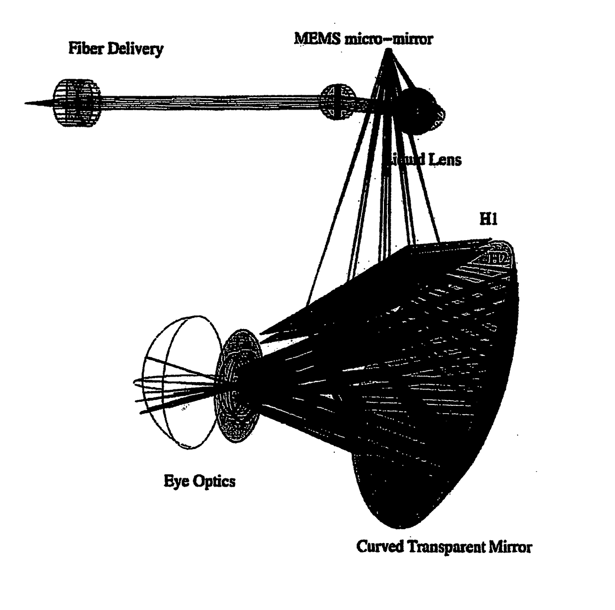
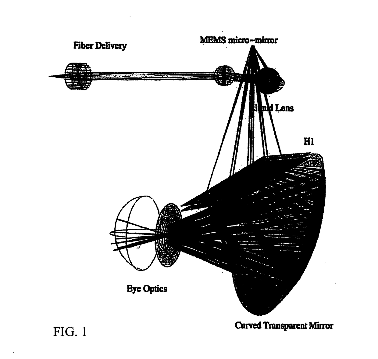
[0045]Applicant's approach to developing an optical see-through HWD attempts to follow a logical path toward the optimum solution. There are many desirable features in a HWD. The waveguide approach entails numerous, possibly unsurmountable limitations, which prevent attainment of many of the key desirable features. The curved combiner approach appears to allow for a solution for providing all of the desirable features.

Desirable Features in a HWD

[0046]Desirable features in an optical see-through HWD include the following:[0047]First and foremost does not harm natural see-through vision[0048]Provide see-through transmission adequate for all conditions, including nighttime[0049]Does not block peripheral vision (so as not to be hit by a car when crossing the street), does not block binocular overlap (to preserve depth perception) and does not block the view downwards (which would interfere with mobility)[0050]Does not cause a discontinuity to see-through vision (a flat beam splitter in ...


PUM


Abstract

An augmented reality head worn device comprising a curve combiner transparent to visible light and reflective in an selected infrared frequency range, a scanning light source defining a field of view, a holographic optical element adapted to provide pupil expansion to create an eye-box, and at least one projection system for providing high acuity at or near a center of the field of view.

Description

CROSS REFERENCE TO RELATED APPLICATIONS[0001]This application claims the benefit of Provisional patent applications: Ser. Nos. 62 / 495,181; 62 / 495,187; 62 / 495,286; 62 / 495,188, 62 / 495,185 all filed Sep. 1, 2016 and the benefit of Provisional Patent Application Ser. No. 62 / 603,160 filed May 17, 2017, and this invention is also a Continuation in Part of Utility patent application Ser. No. 14 / 545,985, filed Jul. 13, 2015 and Ser. No. 15 / 257,883 filed Sep. 6, 2016.FIELD OF THE INVENTION[0002]The present invention relates to head worn displays and in particular to optical see-through head worn devices.BACKGROUND OF THE INVENTION[0003]The most rapid transfer of information to humans is through vision. Head mounted displays are a modality of human-computer interface associated with vision. Head worn display devices are well known. They are display devices worn on the head sometimes as attached to a helmet. They may also be mounted on or be a part of a visor, goggles or eyeglasses. Head worn ...

Claims


Application Information

Patent Timeline
Patent Type & Authority Applications(United States)
IPC IPC(8): H04N9/31G02B27/01G02B27/14G02B27/10
CPCH04N9/3105G02B27/0172G02B27/142G02B27/104H04N13/044H04N13/0484H04N13/0422H04N9/3129H04N9/3188G02B2027/0174G02B2027/0125G02B2027/0112G02B2027/013H04N9/3161B64C1/1484B60J9/00G02B26/0833G02B26/101G02B2027/0123G02B2027/0187H04N13/344H04N13/383H04N13/324
Inventor BELENKII, MICHAELSVERDRUP, LAWRENCEBARNHART, DONALDTAKETOMI, YOSHI
Owner BELENKII MICHAEL
Why Eureka
Try Eureka