Oscillating piston machine

a technology of oscillating pistons and pistons, which is applied in the direction of rotary or oscillating piston engines, rotary piston engines, engines with oscillating pistons, etc., can solve the problems of mass distribution of pistons that is capable of further optimization, and achieve the effect of quiet running of oscillating piston machines

Inactive Publication Date: 2009-07-21
HUTTLIN HERBERT
View PDF10 Cites 9 Cited by
  • Summary
  • Abstract
  • Description
  • Claims
  • Application Information

AI Technical Summary

Benefits of technology

[0015]In the oscillating piston machine according to the invention, the individual pistons which rotate in the housing are accordingly capable of pivoting about a common oscillation axis which lies essentially on a diameter of the spherical housing, as a result of which the pistons have, in contrast to the known oscillating piston machine mentioned at the beginning, a bearing arrangement which is central in the housing. Whereas, in the known oscillating piston machine mentioned at the beginning, the individual pistons are pressed, owing to the centrifugal force as they rotate in the housing, against their oscillation axis bearings which are seated on the inner wall of the housing, the pistons of the oscillating piston machine according to the invention are supported, owing to their central bearing in the housing, toward the center of the housing against the centrifugal forces acting on the pistons, as a result of which the pistons can run with essentially lower friction. Furthermore, the housing of the oscillating piston machine according to the invention is of spherical construction, in contrast to the known oscillating piston machine mentioned at the beginning, which has the advantage that the overall arrangement of the pistons in conjunction with their central bearing in the housing can be constructed with a very particularly homogenous distribution of mass. Furthermore, the spherical configuration of the oscillating piston machine according to the invention provides the advantage of the maximum working volume with significantly more compact overall dimensions of the oscillating piston machine. The individual working chambers can thus be configured with large volumes together with minimum overall dimensions of the oscillating piston machine. Yet a further advantage of the spherical embodiment is that there is a largely free choice with respect to the position of the common oscillating axis in relation to the axis of rotation.
[0054]While the first embodiment has the advantage that the piston can be fabricated in a structurally simple way because there is no need to integrate valves into the pistons but rather only one additional inlet valve has to be provided on the housing, the second embodiment has the advantage that it is in turn possible to use simple flap valves or butterfly valves as the inlet valve, and the function of these valves is independent of the ambient pressure of the housing. On the other hand, in the first embodiment, a controlled valve is preferably used in the form of a solenoid valve, or in the simple case a valve controlled via a camshaft.

Problems solved by technology

Although the known oscillating piston machine has proven favorable in terms of its running properties and its torque curve, it can be considered to be a disadvantage of the known oscillating machine that the mass distribution of the pistons is capable of further optimization owing to the housing geometry and the fact that the individual pistons are borne on the inner wall of the housing.

Method used


Image

  • Oscillating piston machine
  • Oscillating piston machine
  • Oscillating piston machine

Examples


Embodiment Construction

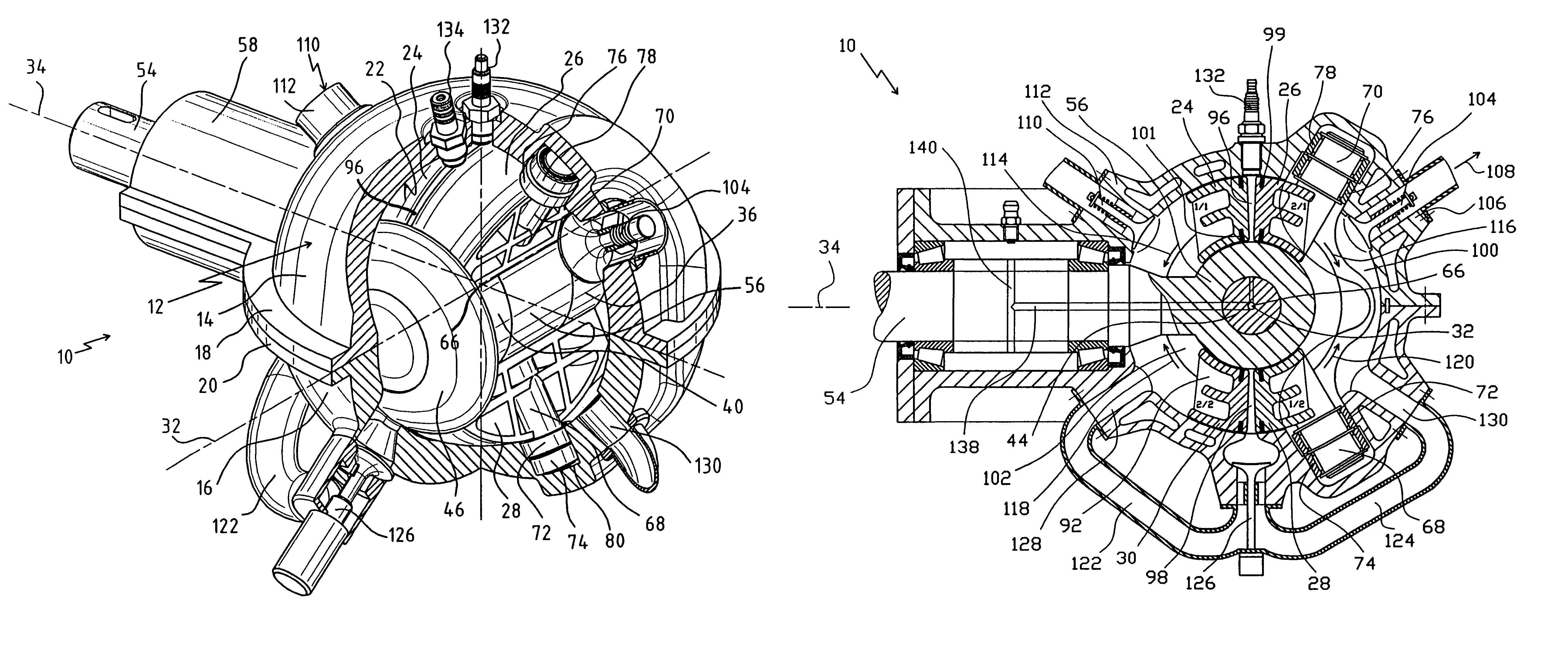
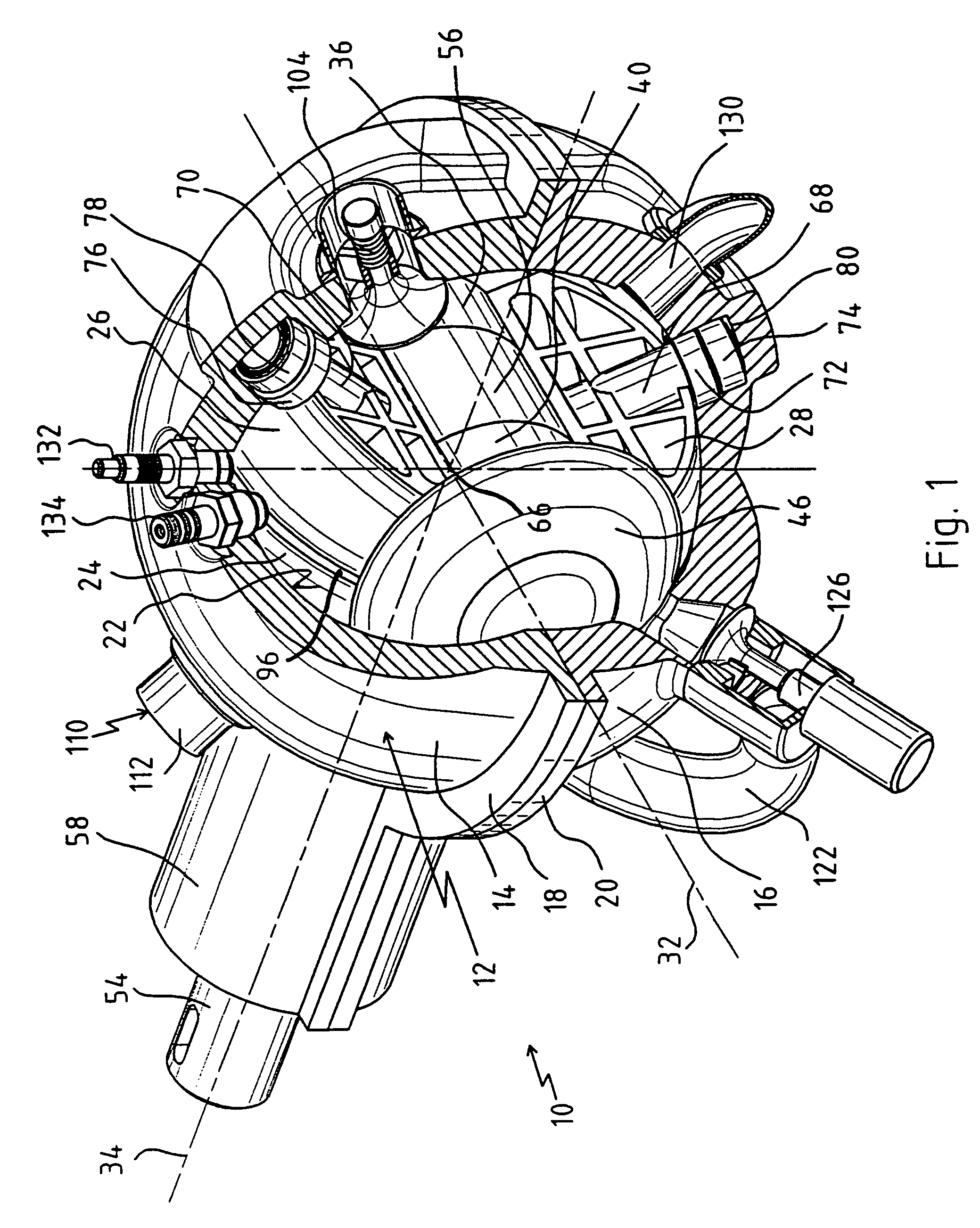
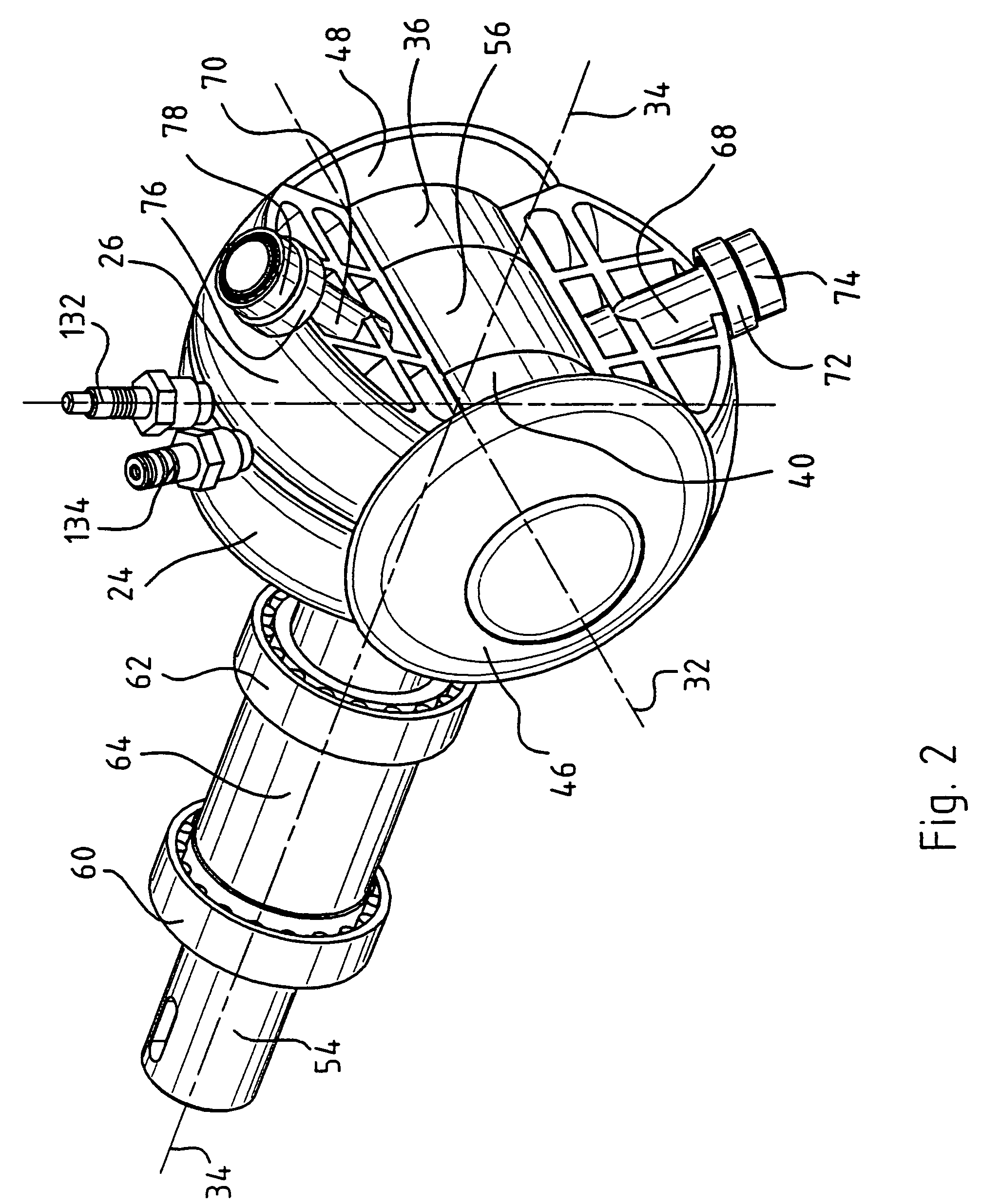
[0076]The embodiment of an oscillating piston machine which is provided with the general reference number 10 will be described in more detail below with reference to FIGS. 1 to 8. The oscillating piston machine 10 serves as an internal combustion engine but can also be used in other applications, for example as a compressor.

[0077]The oscillating piston machine 10 has a housing which is provided with the general reference number 12 and is composed of a first housing half 14 and a second housing half 16.

[0078]The two housing halves 14 and 16 are permanently connected to one another via a respective annular flange 18 or 20.

[0079]An inner wall 22 of the housing 12 is of spherical construction. On the outside the housing 12 of the oscillating piston machine 10 also has spherical symmetry.

[0080]In FIG. 1, the housing 12 is illustrated partially cut away so that in FIG. 1 further details of the oscillating piston machine 10 can be seen inside the housing 12.

[0081]A plurality of pistons, an...


PUM


Abstract

An oscillating piston machine comprises a plurality of pistons which are arranged in a housing, rotate together in the housing about an axis of rotation which is essentially central in the housing and is fixed to the housing, and execute reciprocating oscillating movements about a respective oscillation axis as they rotate in the housing, in each case two adjacent pistons executing oscillating movements in opposite directions. The housing is of spherical construction on the inside, the oscillation axes of the pistons being formed by a common oscillation axis which run essentially through the center of the housing.

Description

CROSS REFERENCE TO RELATED APPLICATION[0001]The present application is a continuation of international patent application PCT / EP02 / 01226 filed on Feb. 6, 2002 which designates the United States.BACKGROUND OF THE INVENTION[0002]The invention relates to an oscillating piston machine, comprising a plurality of pistons which are arranged in a housing, rotate together in the housing about an axis of rotation which is essentially central in the housing and is fixed with respect to the housing, and execute reciprocating oscillating movements about a respective oscillation axis as they rotate in the housing, in each case two adjacent pistons executing oscillating movements in opposite directions.[0003]Oscillating piston machines belong to a generic type of internal combustion engines in which the individual working strokes of the taking in, compression, ignition, expansion and expulsion of the combustion mixture are brought about by reciprocating oscillating movements of the individual pist...

Claims


Application Information

Patent Timeline
Patent Type & Authority Patents(United States)
IPC IPC(8): F01C3/00F03C2/00F03C4/00F01C3/02F01C3/06F02B53/00F01C9/00
CPCF01C9/005F01C3/02
Inventor HUTTLIN, HERBERT
Owner HUTTLIN HERBERT
Why Eureka
Try Eureka