Air cleaner

a technology for air cleaners and air passages, applied in separation processes, filtration separation, transportation and packaging, etc., can solve the problems of increased performance deterioration, difficult to sufficiently secure the air passage area, and easy loss of pressure at the time of taking in air, so as to reduce the risk of foreign objects breaking, reduce the risk of damage, and reduce the effect of air pollution

Inactive Publication Date: 2009-07-21
KOMATSU LTD
View PDF11 Cites 15 Cited by
  • Summary
  • Abstract
  • Description
  • Claims
  • Application Information

AI Technical Summary

Benefits of technology

[0014]It is therefore an object of the present invention to overcome the above-mentioned drawbacks by providing air cleaner that can reduce restriction at the time of taking in air and improve engine performance, and can prolong the element cleaning interval and improve maintainability, and is appropriate for a machine that is used at dusty places.
[0018]In the present invention, it is desired that, at the downstream of the filter element, there is arranged a safety filter for preventing the break-in of foreign matters when the filter element is detached.
[0019]According to the present invention, since air inflowing from the top side of the mountain portions of the filter element can outflow also from at least one end of the filter element, path area (filtering area) can be increased, which can provide an air cleaner of small path resistance. According to the present invention, there may be employed a case in which filtered air is made to outflow from only one end (refer to sixth embodiment shown in FIG. 12K to FIG. 12N). In this case, since the direction of entire air inflowing from the top side is surely changed in the filter element to make filtered air outflow, the air cleaner can be made compact in configuration in case of taking in air from upward and sending out filtered air in the horizontal direction, and is desirably used for machines working at dusty places.
[0020]Furthermore, according to the present invention, air is made to inflow from the top side of the mountain portions of the cylindrical filter element as well as from the end of one end side thereof, and filtered air is made to outflow from the end of the other end side as well as from the inner circumference of the hollow portion. Thus, path area for filtered air can be made significantly large, which can provide an air cleaner of further smaller restriction.
[0021]Especially, according to the present invention, since one end side of the filter element is supported by the hollow portion, the flow of air to the one end side can be made smooth, and the capacity of the bottom of the casing can be made large and dust and so on can be accumulated sufficiently, and a discharge port for discharging dust and so on can be arranged at a desirable position.
[0022]Furthermore, according to the present invention, since there is formed a safety filter, when changing the filter element, foreign matters can be prevented from breaking thereinto. According to the present invention, in case of arranging the safety filter, the safety filter is not arranged in the hollow portion of the filter element, which can enlarge the thickness of the filter element and can increase path area.

Problems solved by technology

However, there is raised the following problem in the configuration disclosed in the document 1.
That is, since both end surfaces of the cylindrical filter elements on the longitudinal direction are closed, the air comes to pass from the outer circumference side to the inner circumference side of the elements, which makes it difficult to sufficiently secure the air-passing area.
As a result, pressure loss at the time of taking in air is prone to be large, and there may be raised performance deterioration when used for an engine to take in air.
Furthermore, clogging frequently takes place in the elements, which raised a problem that the element cleaning interval is shortened.

Method used


Image

  • Air cleaner
  • Air cleaner
  • Air cleaner

Examples


first embodiment

[0039]A first embodiment of the present invention will further be described below with reference to the accompanying drawings. As for the second to seventh embodiments, parts or components similar to those of the first embodiment are indicated with the same reference numerals, and detailed explanation of which will be abridged or omitted.

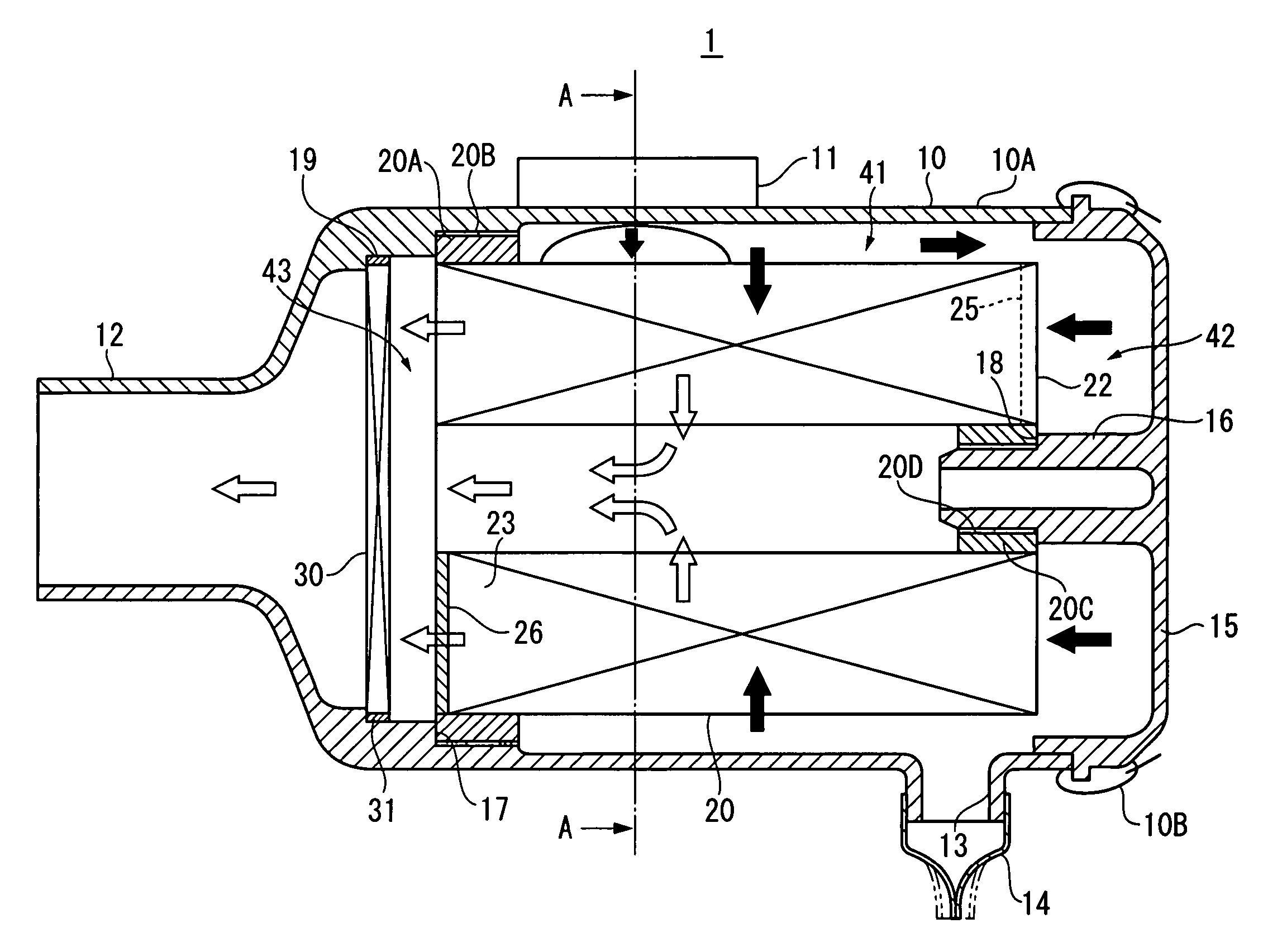
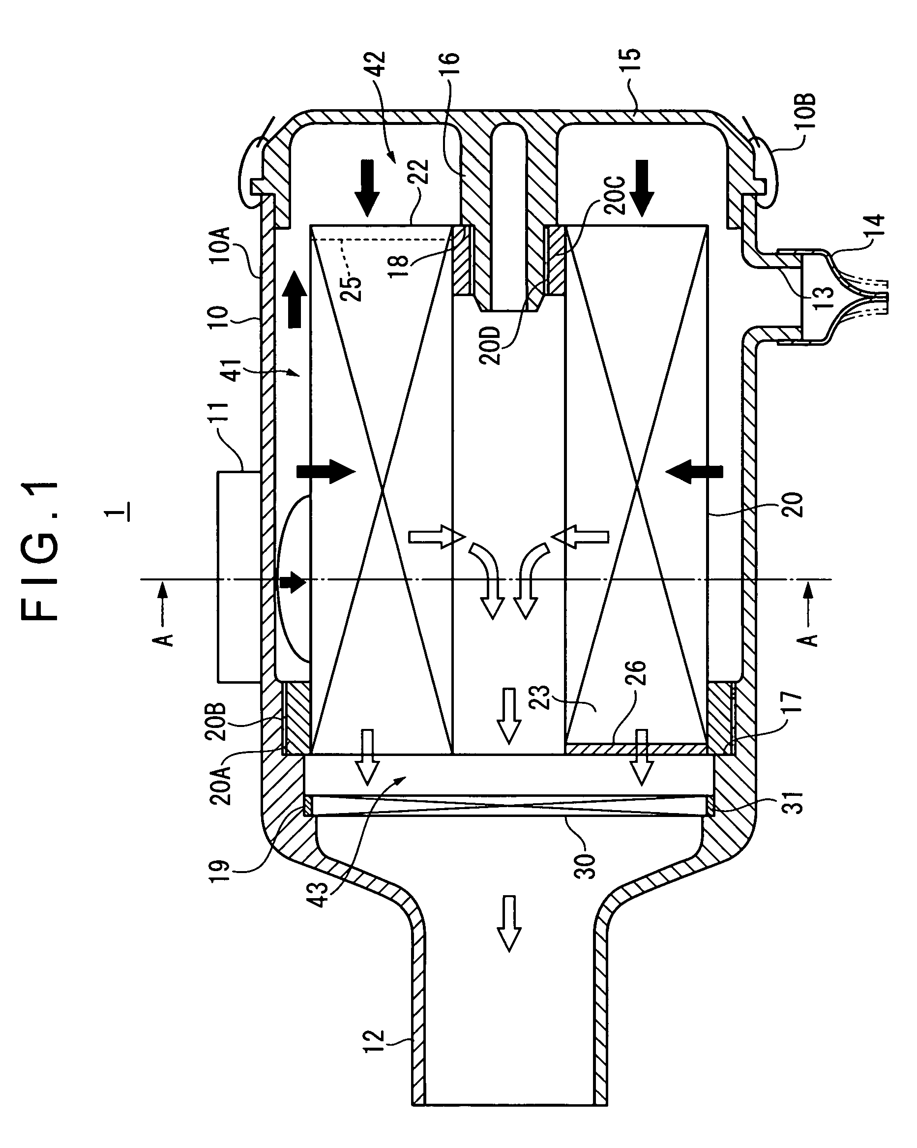
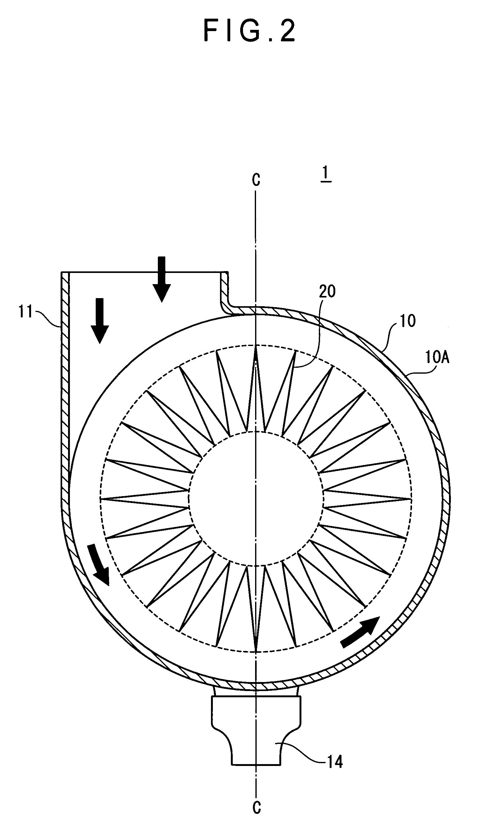
[0040]FIG. 1 shows a cross-sectional view of an air cleaner 1 of the first embodiment. FIG. 2 shows an A-A line diagram viewed along arrows in FIG. 1.

[0041]The air cleaner 1 shown in FIG. 1 and FIG. 2 is placed on a construction machine that is used at dusty construction places, and includes a cylindrical casing 10 having a casing body 10A whose one end is opened, a filter element 20 arranged inside the casing 10, and a safety filter 30 arranged at the downstream side of the filter element 20 inside the casing 10.

[0042]At the outer circumference of the casing 10, there is formed an air inlet pipe 11 that is located eccentrically against a center C-C...

second embodiment

[0062]FIG. 7 shows a cross-sectional view of an air cleaner 2 of a second embodiment according to the present invention. FIG. 8 shows a B-B line diagram viewed along arrows in FIG. 7.

[0063]In the air cleaner 2 shown in FIG. 7 and FIG. 8, at the inner circumference of one end of the casing body 10A located on the cover 15 side, there is formed a supporting portion 51 for supporting the outer circumference of the filter element 20. At the outer circumference of the filter element 20, there is fixed an outer circumference retention member 61. When the filter element 20 is housed in the casing 10, the outer circumference retention member 61 is made to abut on the supporting portion 51, and one end of the filter element 20 is retained. At one end of the cover 15 located on the casing body 10A side, there is formed an abutting portion 52. When the cover 15 is mounted to the casing body 10A, the abutting portion 52 is made to abut on the side of the outer circumference retention member 61 ...

third embodiment

[0065]In an air cleaner 3 in a third embodiment shown in FIG. 9, the shape of the casing 10 and the filter element 20 is different from that in the first and second embodiments.

[0066]That is, the casing body 10A of the casing 10 in the third embodiment is substantially in the shape of a box whose upper portion is opened, and the air outlet pipe 12 is formed at the lower portion of the casing 10. There is formed the air inlet pipe 11 at the cover 15 that closes the opened portion of the casing body 10A.

[0067]In the casing 10, there is arranged a housing 53 in which a filter element 20 in the form of a rectangular solid is housed. In the housing 53, there is formed an upper opening 54 through which the filter element 20 is mounted from upward, a lower opening 55 to make filtered air outflow downward, an inlet opening 56 that faces opened end of the valley portions 23 of the filter element 20, and an outlet opening 57 that faces opened end of the mountain portions 22.

[0068]There is for...


PUM

PropertyMeasurementUnit
heightaaaaaaaaaa
circumferenceaaaaaaaaaa
flexibleaaaaaaaaaa

Abstract

The present invention provides an air cleaner, in which a casing has an air inlet pipe making air inflow along a direction perpendicular to the axis of a cylindrical filter element, and an air outlet pipe making filtered air outflow along the axis, and the casing has a supporter clingingly supporting the end outer circumference of the filter element on closed valley portions side along the circumference direction continuously, and another supporter supporting the end inner circumference of the filter element on closed mountain portions side along the circumference direction continuously to close a hollow portion, and air to be filtered inflows to the filter element from a first inflow space on the top side of the mountain portions as well as from the end of a second inflow space side, and filtered air outflows from the end on an outflow space side as well as from the hollow portion.

Description

BACKGROUND OF THE INVENTION[0001]1. Field of the Invention[0002]The present invention relates to an air cleaner, and more particularly, to an air cleaner for an engine of a vehicle that is used at dusty places.[0003]2. Description of Related Art[0004]Concerning the configuration of an air cleaner and a filter element used therein, there have been conventionally known, for example, a double-elements type air cleaner as disclosed in Japanese Unexamined Utility Model Application No. S59-133762, on pages 6 to 7, FIG. 2, FIG. 3 and others (hereinafter referred to as document 1), and a serial type air cleaner as disclosed in Japanese Unexamined Patent Application No. 2000-508974, on page 12, FIG. 1 and others (hereinafter referred to as document 2).[0005]FIG. 14 shows a cross-sectional view of a double-cylinder type air cleaner 70 disclosed in the document 1. As shown in FIG. 14, a cylinder-shaped casing 71 has an inlet pipe 72 formed on the side thereof, and an outlet pipe 73 formed on t...

Claims


Application Information

Patent Timeline
Patent Type & Authority Patents(United States)
IPC IPC(8): B01D46/00B01D46/24
CPCB01D46/0004B01D46/24B01D46/008B01D46/0024B01D46/64B01D46/88
Inventor NISHIYAMA, TOSHIHIKOMATSUSHIMA, SHIGEO
Owner KOMATSU LTD
Why Eureka
Try Eureka