
Method for variable valve actuation to provide positive power and engine braking

a variable valve and actuation technology, applied in the direction of valve arrangement, machine/engine, output power, etc., can solve the problems of difficult adjustment of timing and/or amount of engine valve lift, system utilizing high-speed control mechanism, cost-effective manufacturing and operation, and little development of methods of operating the engine valv

Active Publication Date: 2009-07-28
JACOBS VEHICLE SYST
View PDF4 Cites 52 Cited by
  • Summary
  • Abstract
  • Description
  • Claims
  • Application Information

AI Technical Summary

Benefits of technology

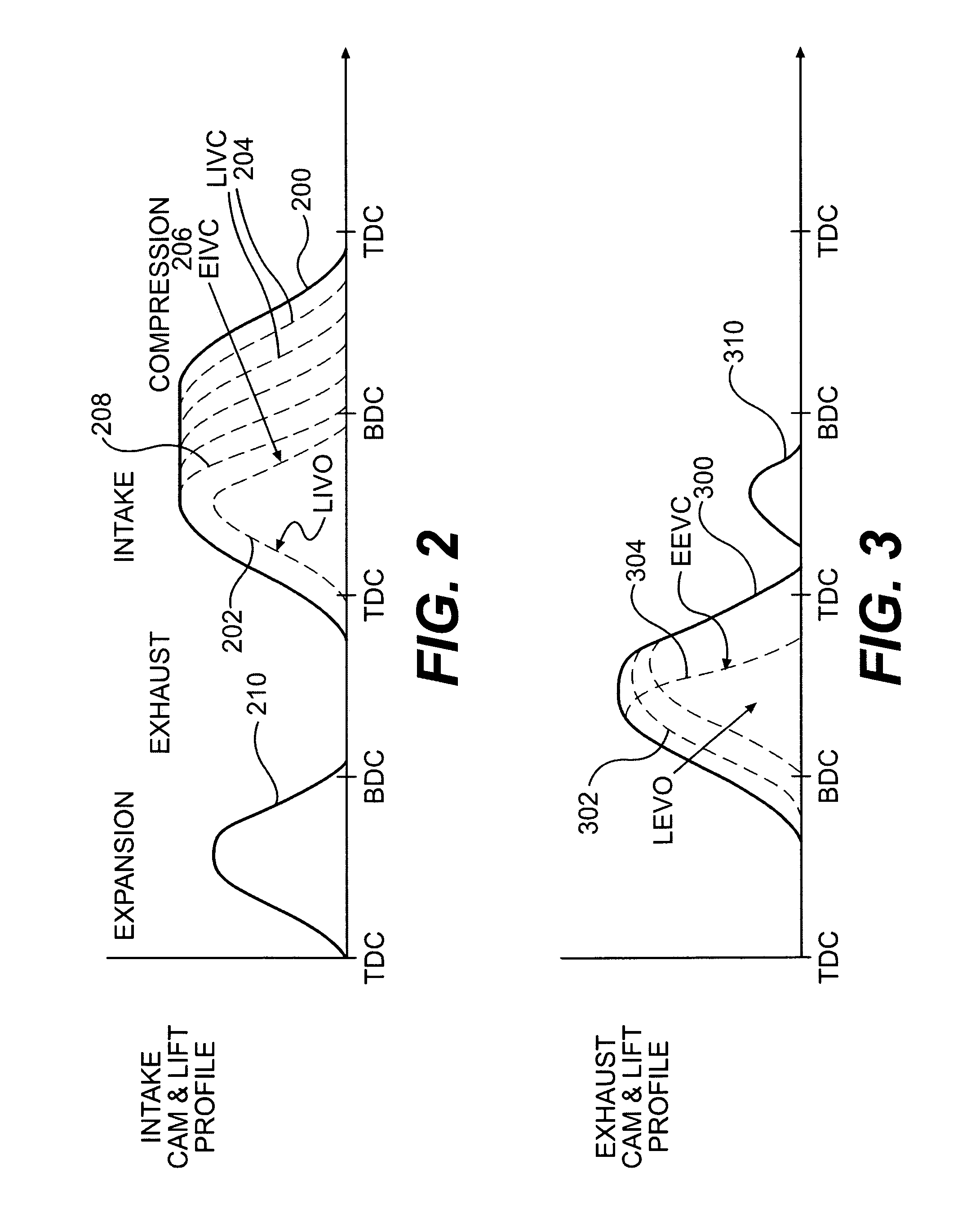
[0015]Responsive to the foregoing challenges, Applicant has developed a method of variable valve actuation of one or more valves, such as an intake valve, an exhaust valve and a brake valve. The method includes variable valve actuation during a positive power mode, an engine braking mode and transitions between these modes. When transitioning from positive power mode to engine braking mode, a late intake valve opening (LIVO) is actuated, an early intake valve closing (EIVC) is actuated, an early exhaust valve closing (EEVC) is actuated and the brake valve is enabled. When transitioning from engine braking mode to positive power mode, the late intake valve opening (LIVO) is actuated, the early i...

Problems solved by technology

The use of fixed profile cams, however, can make it difficult to adjust the timings and / or amounts of engine valve lift to optimize them for various engine operating conditions.
Systems utilizing high speed control mechanisms, however, can be costly to manufacture and operate.
While there has been substantial development of methods of operating engine valves for both positive power operation and engine braking operation, there has been little development of methods of operating engine valves during the time that the engine is transitioning between positive power operation and engine braking.
During this transition time, one or more of the engine valves and the valve trains associated with them may be subjected to undesirable loads if the engine valve actuation is immediately switched between positive power operation and engine braking operation.
The undesirable loads, if repeated or sufficiently severe can cause engine damage and / or failure.

Method used


Image

  • Method for variable valve actuation to provide positive power and engine braking
  • Method for variable valve actuation to provide positive power and engine braking
  • Method for variable valve actuation to provide positive power and engine braking

Examples


Embodiment Construction

[0026]Reference will now be made in detail to embodiments of the system and method of the present invention, examples of which are illustrated in the accompanying drawings. As embodied herein, the present invention includes systems and methods for providing the actuation of one or more engine valves.

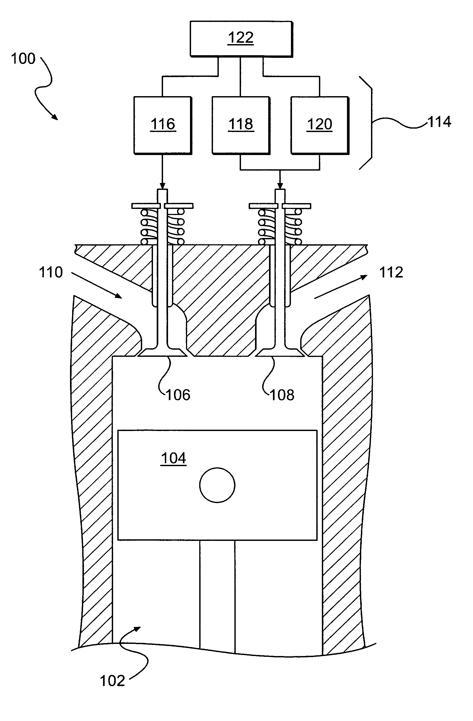
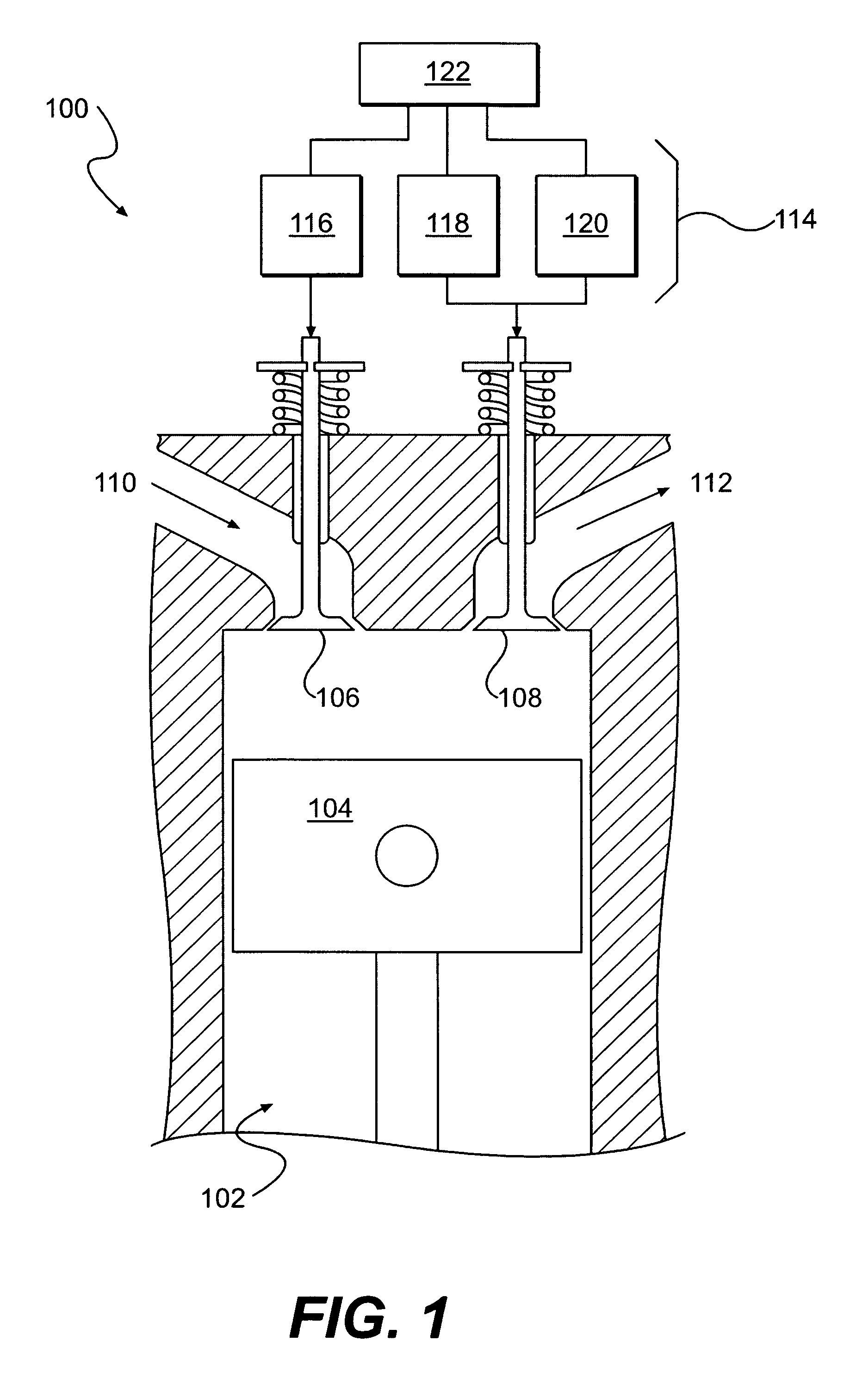
[0027]FIG. 1 is an embodiment of a valve actuation system 100 capable of implementing embodiments of methods of positive power engine operation, engine braking operation, and transitioning between positive power and engine braking operation. The valve actuation system 100 may have a cylinder 102 in which a piston 104 may reciprocate upward and downward repeatedly during the time the engine is in operation. At the top of the cylinder 102, there may be at least one intake valve 106 and at least one exhaust valve 108. The intake valve 106 and the exhaust valve 108 may be opened and closed to provide communication with an intake gas passage 110 and an exhaust gas passage 112, respectively. T...


PUM


Abstract

A control method for transitioning from positive power to engine braking (and vice-versa) is disclosed. This transition may be made using variable valve actuation and two-stroke braking. The process may involve three engine operation modes: positive power (i.e., firing or non-braking), engine braking, and transition between engine braking and positive power. The intake and exhaust valve actuations provided for each of the different modes of operation may be different from each other.

Description

FIELD OF THE INVENTION[0001]The present invention relates generally to methods for actuating one or more intake, exhaust and / or auxiliary valves in an engine. In particular, the present invention relates to methods for providing variable valve actuation for transitioning between positive power operation and engine braking operation of engine valves.BACKGROUND OF THE INVENTION[0002]Valve actuation in an internal combustion engine is required in order for the engine to produce positive power, engine braking, exhaust gas recirculation (EGR), and / or brake gas recirculation (BGR). During positive power, one or more intake valves may be opened to admit fuel and air into a cylinder for combustion. One or more exhaust valves may be opened to allow combustion gas to escape from the cylinder. Intake, exhaust, and / or auxiliary valves may also be opened for exhaust gas recirculation events during positive power at various times to recirculate gases from the exhaust manifold into the engine cyli...

Claims


Application Information

Patent Timeline
IPC IPC(8): F02D13/04F02D13/06
CPCF02D13/04F02D13/0207
Inventor YANG, ZHOU
Owner JACOBS VEHICLE SYST
Learn More