Wall mountable acoustic assembly for indoor rooms

Active Publication Date: 2009-07-28
PERDUE JOAB JAY
View PDF30 Cites 20 Cited by
  • Summary
  • Abstract
  • Description
  • Claims
  • Application Information

AI Technical Summary

Benefits of technology

[0013]b) at least one mounting bracket adapted to removably attach to said rear surface and said wall in a manner to space said panel away from the wall and downwardly angled along a plane of symmetry towar

Problems solved by technology

It is well known that rooms can produce distortional acoustic effects such as echoes, reverberations, amplified bass tones, and uneven volume distribution throughout the room.
Such

Method used


Image

  • Wall mountable acoustic assembly for indoor rooms
  • Wall mountable acoustic assembly for indoor rooms
  • Wall mountable acoustic assembly for indoor rooms

Examples


Embodiment Construction

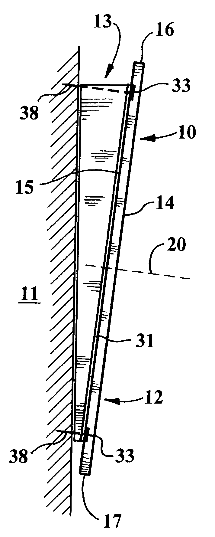
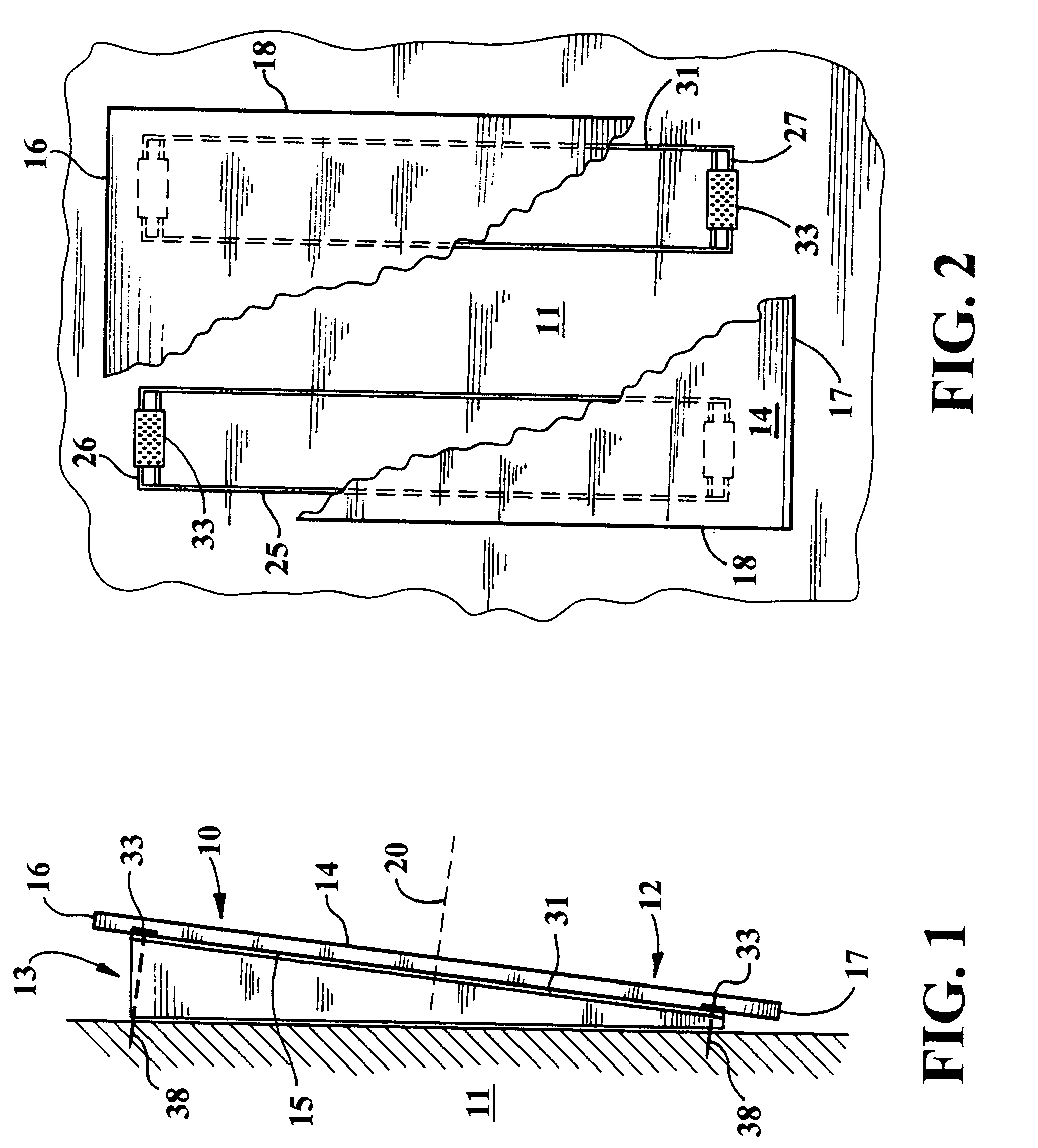
[0024]Referring now to FIGS. 1 and 2, an acoustic assembly 10 of the present invention is shown mounted upon a wall 11 and comprised of panel 12 and mounting bracket 13.

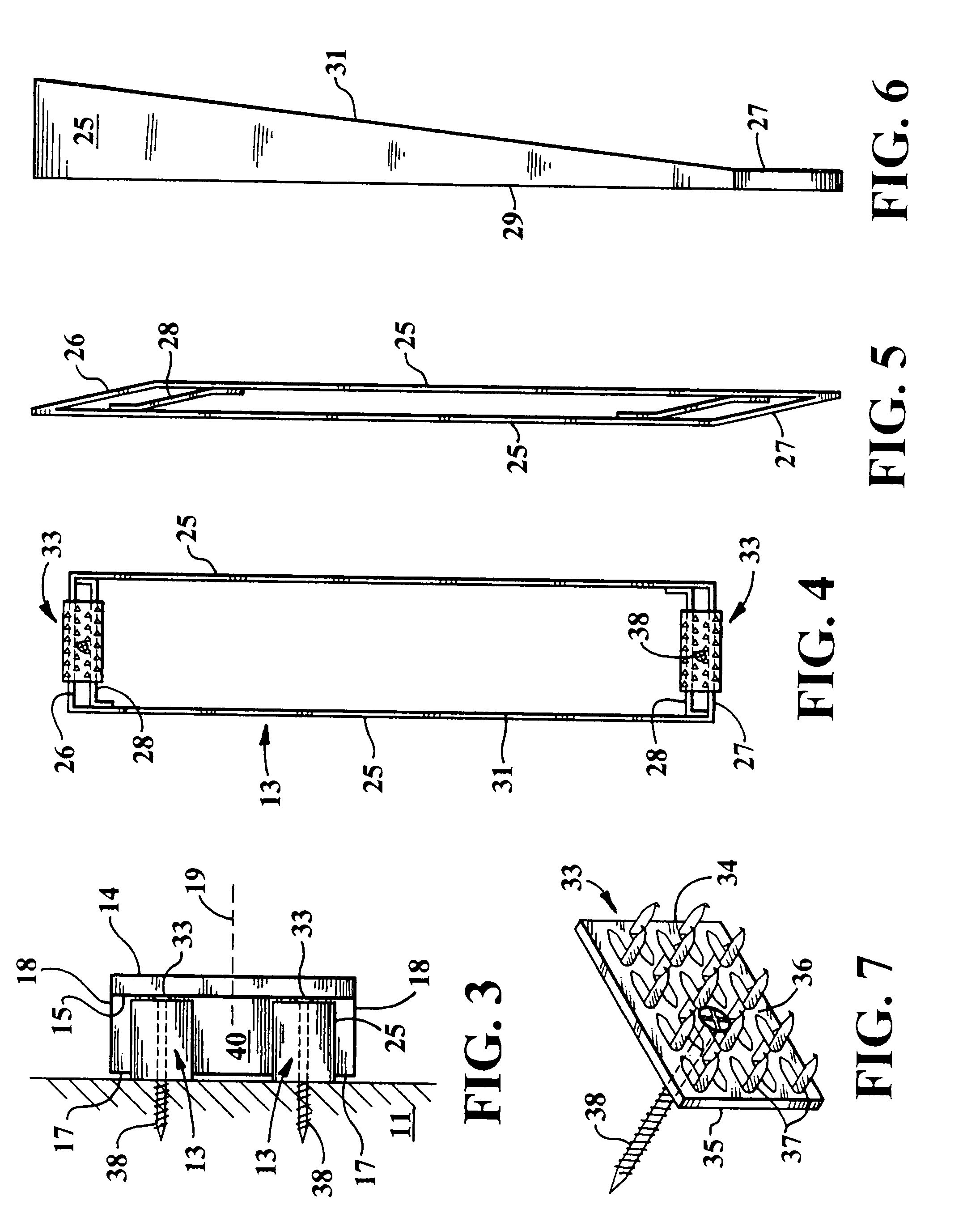
[0025]Panel 12 is a self-supported structure bounded in part by flat front and rear surfaces 14 and 15, respectively, and defining therebetween a uniform thickness of between one and two inches. The illustrated embodiment of said panel is of rectangular contour, having a perimeter comprised of top and bottom edge surfaces, 16 and 17, respectively, and side edge surfaces 18. Such rectangular configuration accordingly has two planes of symmetry, shown as vertical plane 19 and horizontal plane 20. The panels may have vertically measured lengths of about 4 feet and horizontally measured widths between 2 and 8 feet.

[0026]Panel 12 is preferably fabricated of inter-bonded fibrous material capable of absorbing sound energy. Suitable fibrous materials include, for example, rock wool and fiberglass. Bonding agents such as ther...


PUM


Abstract

An acoustic assembly including a thin sound absorbing panel supported by foldable mounting brackets is adapted to be mounted upon the walls of an indoor listening enclosure. The space behind the panel functions as an acoustic diffusion chamber which augments the acoustic performance of the panel. A number of such assemblies are employed in a manner such that the panels are offset from the wall and downwardly angled.

Description

BACKGROUND OF THE INVENTION[0001]1. Field of the Invention[0002]This invention relates to the improvement of acoustic qualities of an indoor room, and more particularly concerns components which can be assembled and installed upon the walls of a room for improving the acoustic quality thereof.[0003]2. Description of the Prior Art[0004]In indoor rooms intended primarily for listening to music, whether residential rooms used for watching television or listening to recorded music, or public auditoriums or enclosures employed for listening to live music, it is desired that the quality of the heard sound be as accurate as the produced sound.[0005]It is well known that rooms can produce distortional acoustic effects such as echoes, reverberations, amplified bass tones, and uneven volume distribution throughout the room. Systems for improving the sound quality of indoor rooms have been disclosed in U.S. Pat. Nos. 4,605,088; 4,682,670; 5,035,298; 5,896,710; 6,530,451; 6,782,871 and elsewher...

Claims


Application Information

Patent Timeline
IPC IPC(8): E04B1/82E04B1/99
CPCE04B1/86E04B1/99F16B15/0046E04B2001/829
Inventor PERDUE, JOAB JAY
Owner PERDUE JOAB JAY
Why Eureka
Try Eureka