Condensing deaerating vent line for steam generating systems

a steam generator and condensing technology, applied in the direction of separation process, dispersed particle separation, chemical apparatus and processes, etc., can solve the problems of varies in corrosivity of volatile components, and failure of the turbine or other parts of the steam system, so as to minimize the volume of steam vented and heat loss. , the effect of efficient venting of impurities

Inactive Publication Date: 2006-04-27
SIEMENS ENERGY INC
View PDF9 Cites 5 Cited by
  • Summary
  • Abstract
  • Description
  • Claims
  • Application Information

AI Technical Summary

Benefits of technology

[0010] With the foregoing in mind, methods and apparatuses consistent with the present invention provide for efficiently venting impurities derived from feed water from a HRSG system by concentrating the impurities into a condensing deaerating vent line and then venting a proportion

Problems solved by technology

Concentrations as small as 10 parts per billion (ppb, μg/kg) are considered high, while a concentration of 100 ppb may quickly initiate corrosion that eventually leads failure of the turbine or other parts of the steam system.
The corrosivity of volatile components varies, but some are clearly corrosive.
This needs to be performed at startup of the HRSG, since the drum needs to be of sufficient temperature, and the HRSG system cannot operate while the drum

Method used


Image

  • Condensing deaerating vent line for steam generating systems
  • Condensing deaerating vent line for steam generating systems
  • Condensing deaerating vent line for steam generating systems

Examples


Embodiment Construction

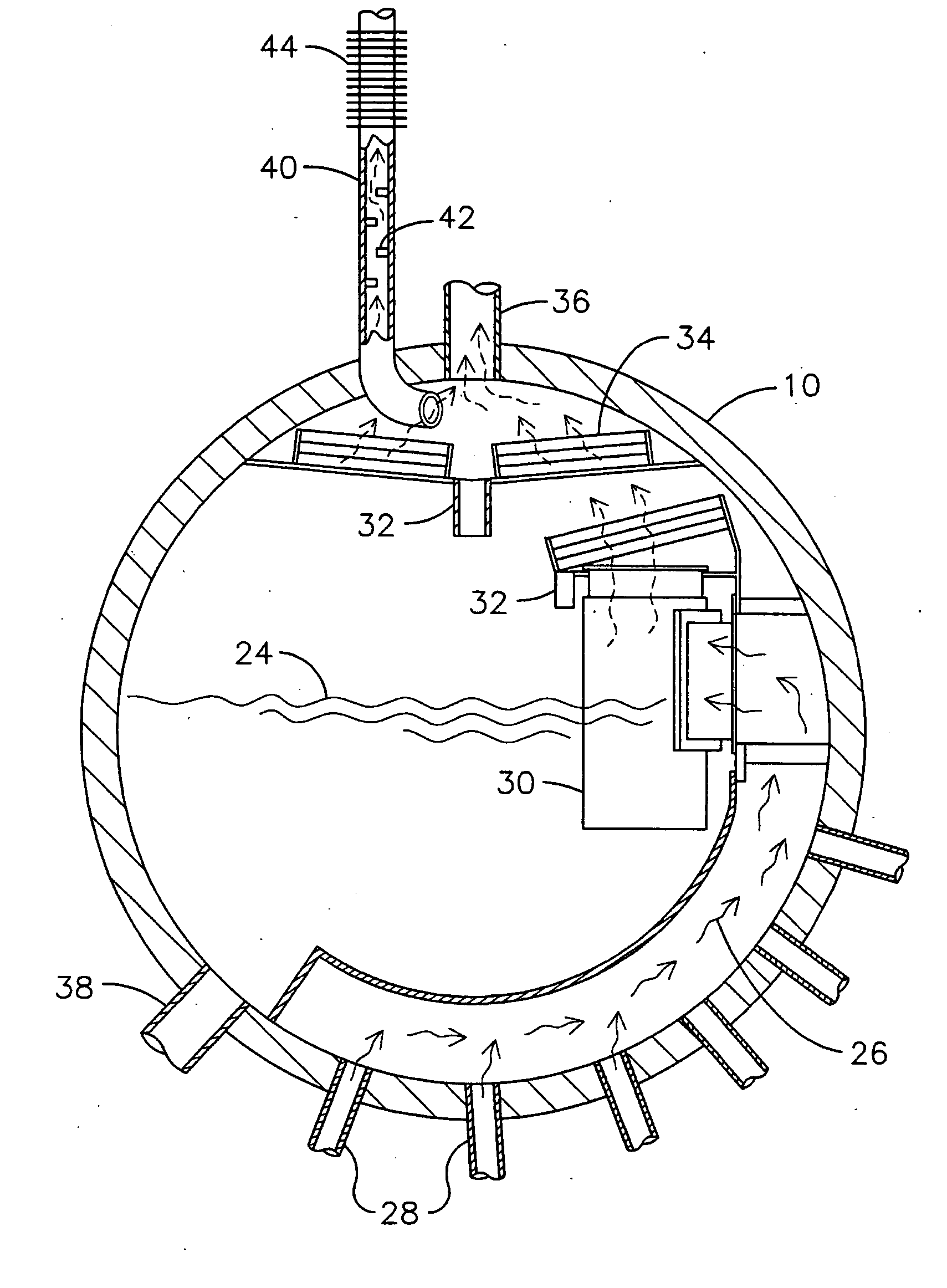
[0020] In order to purge a HRSG of volatile impurities that are present in feed water and are otherwise obtained from the environment, large quantities of steam need to be vented from the drums of the HRSG. This venting is only done during start-up of the HRSG, since large quantities of steam cannot be vented during normal operation. Without mass venting, the impurities build up in the system and cause corrosion of parts and other malfunctions. However, mass venting can cause the loss from the HRSG system of more than six million pounds (2.7 million kg) of otherwise useable steam each year.

[0021] The present invention seeks to avoid most of this wasted steam by providing a method and apparatus for continuously venting a small amount of steam that has a high concentration of the volatile impurities. By venting only a small amount of steam, millions more pounds of steam can be put to the use of producing energy. Further, since only a small amount of steam is being vented to the envir...


PUM

PropertyMeasurementUnit
Lengthaaaaaaaaaa
Lengthaaaaaaaaaa
Pressureaaaaaaaaaa

Abstract

The present invention comprises an apparatus and method for efficiently venting impurities from a heat recovery steam generator system by concentrating the impurities in a condensing deaerating vent line 40 and then venting a proportionately small amount of steam with a proportionately high concentration of impurities. The condensing deaerating vent line 40 is attached to a low pressure drum 10, and feed water 54 may be added to the upper portion of the condensing deaerating vent line 40 to improve condensation and conserve thermal energy.

Description

FIELD OF THE INVENTION [0001] The present invention relates to heat recovery steam generators (HRSG), and more particularly to the venting of volatile impurities within the HRSG. BACKGROUND OF THE INVENTION [0002]FIG. 1 illustrates a heat recovery steam generator (HRSG), which is used to turn otherwise wasted hot gasses into useful steam. Hot gasses enter 2 the HRSG from sources such as a gas turbine (not shown). In a HRSG, the hot gasses pass over heat transfer surfaces made up of tubes, usually with fins, in which water, under pressure is converted to steam. The heat from the hot gasses are transferred to either water, steam, or a combination of water and steam in a boiler tube, which is a type of heat exchanger. The steam rises in the tubes and is collected in a series of three drums, usually a high pressure (HP) drum 6, an intermediate pressure (IP) drum 8, and a low pressure (LP) drum 10. Ultimately, the hot gasses, after being depleted of most of their useful heat, are vented ...

Claims


Application Information

Patent Timeline
IPC IPC(8): B01D45/00
CPCB01D45/06B01D53/002
Inventor BELLOWS, JAMES C.SHOEMAKER, FRED W.
Owner SIEMENS ENERGY INC
Why Eureka
Try Eureka