Battery can having off-center C-shaped vent

a technology of electrochemical cells and vents, which is applied in the field of electrochemical cells, can solve the problems of consuming a significant amount of useable volume within the battery, affecting the safety of electrochemically active materials, and affecting the safety of electrochemical cells, so as to improve the protection safeguards of electrochemical cells, reduce the effect of gas venting and enhanced venting mechanism

Active Publication Date: 2011-01-25
H&T WATERBURY +2
View PDF28 Cites 3 Cited by
  • Summary
  • Abstract
  • Description
  • Claims
  • Application Information

AI Technical Summary

Benefits of technology

[0008]The present invention improves the protective safeguards of an electrochemical cell with an enhanced vent mechanism formed in the closed end wall of the cell container that achieves effective venting of gases from the container. To achieve this and other advantages, in accordance with the purpose of the present invention as embodied and described herein, the present invention provides for an electrochemical cell including a container having a first end, a second end, a side wall extended between the first and second ends, and an end wall extending across the first end. The cell also has a positive electrode, a negative electrode and an alkaline electrolyte disposed in the container. The cell further includes a pressure relief vent mechanism formed in the end metal wall of the container for releasing internal pressure from within the container when the internal pressure becomes excessive. The pressure relief vent mechanism has a reduced thickness groove formed substantially in a C-shape having first and second ends and a curved portion between the first and second ends. Additionally, the groove is offset from the center of the end metal wall such that the curved portion of the C-shaped reduced thickness groove midway between the ends is closer to the center of the end metal wall than the first and second ends.
[0009]According to another aspect of the present invention, a metal can is provided having a pressure relief vent mechanism for use as an electrochemical cell container. The metal can includes a side wall, an open end and a closed end having an integral metal end wall. A pressure relief vent mechanism is formed in the metal end wall of the container. The reduced thickness groove is formed substantially in a C-shape having first and second ends and a curved portion extending between the first and second ends. The groove is offset from the center of the metal end wall such that the curved portion of the C-shape is closer to a center of the end wall than the first and second ends. The formation of the C-shaped groove offset from the center of the metal end wall advantageously allows for proper venting of excessive gases for some battery cells, particularly those employing a cover overlying the pressure relief vent mechanism.

Problems solved by technology

With the can sealed closed, excessive build-up of high pressure gases within the sealed can may lead to damage to the cell and / or the device in which the cell is employed.
The conventional approach of employing a vent in the seal structure requires an assembly that generally consumes a significant amount of useable volume within the battery can.
This results in less space available for the electrochemically active materials, thus limiting battery service life capability.
Such thin vents may be susceptible to damage such as during cell manufacturing (e.g., impact molding), and therefore may be unacceptable for some cells.
However, due to bulging of the can and resultant flexing of the bottom end wall, and further due to improved low profile walls, and the symmetric spacing of the adjacent welds (e.g., 120°), the peripheral flange of the overlying cover may form a seal against the bottom end wall of the can and prevent proper venting of gas to the outside environment.
Thus, proper venting of excessive gases may be inhibited which could lead to a possible crimp release.

Method used


Image

  • Battery can having off-center C-shaped vent
  • Battery can having off-center C-shaped vent
  • Battery can having off-center C-shaped vent

Examples


Embodiment Construction

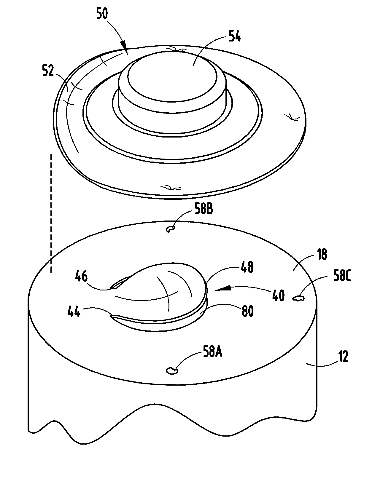
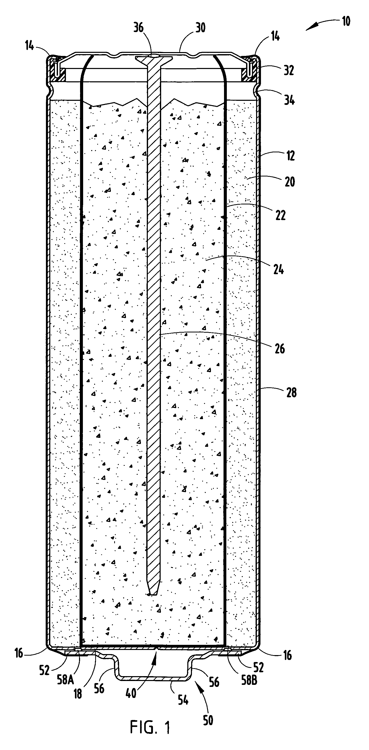
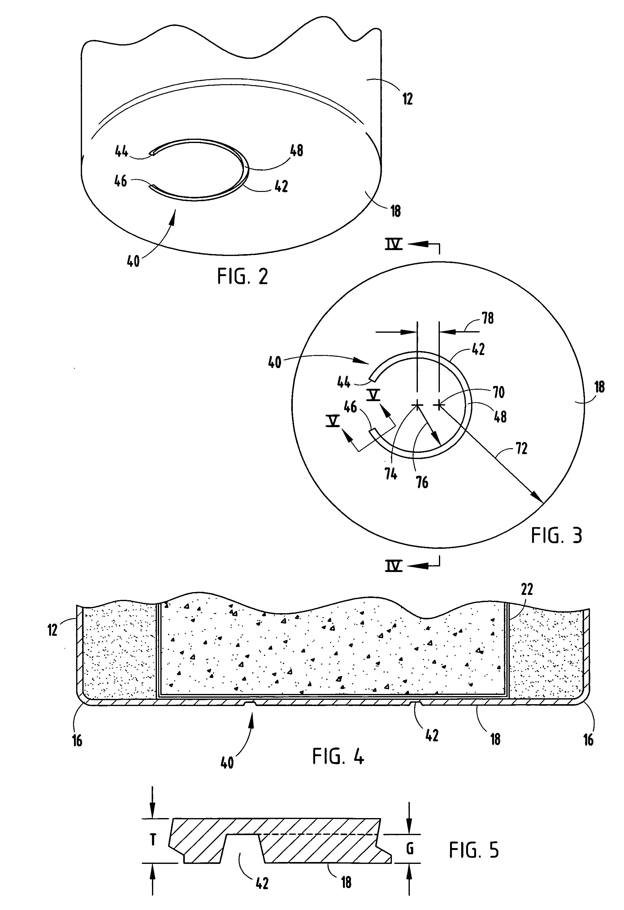
[0020]Referring to FIG. 1, a cylindrical alkaline electrochemical cell (battery) 10 is generally shown having a stress concentration pressure relief vent mechanism 40 formed in the closed bottom end wall of the cell can 12 and an overlying outer cover 50 welded to the can bottom end wall, according to one embodiment of the present invention. The pressure relief mechanism 40, formed as a reduced thickness groove, operates as a pressure rupturable vent to vent excessive gas from within the battery cell and, in cooperation with the outer cover 50, provides for the effective release of excessive gases. The electrochemical cell 10 may include a cylindrical alkaline cell, such as an AA-size battery cell, according to one example. It should be appreciated that other shapes and sizes of cells for use in single or multiple cell batteries may employ the vent 40 and cover 50 arrangement according to the teachings of the present invention.

[0021]The electrochemical cell 10 includes a container g...


PUM

PropertyMeasurementUnit
thicknessaaaaaaaaaa
thicknessaaaaaaaaaa
thicknessaaaaaaaaaa

Abstract

An electrochemical cell is provided with an enhanced pressure relief vent formed in a closed end of the cell container that allows for effective venting of gas from the closed end of the container. The cell includes a container having a first end, a second end, a side wall extending between the first and second ends, and an end wall extending across the first end. The cell has a positive electrode, a negative electrode, and an aqueous alkaline electrolyte, all disposed in the container. The cell further includes a pressure relief vent mechanism having an offset C-shaped reduced thickness groove formed in the end wall of the container. A cover can be welded to the closed end wall of the container over the pressure relief vent mechanism.

Description

BACKGROUND OF THE INVENTION[0001]The present invention generally relates to electrochemical cells (batteries) and, more particularly, relates to an alkaline electrochemical cell having a pressure relief vent formed in the cell container for effectively venting gases at excessive pressure.[0002]Alkaline electrochemical cells employ a container typically in the form of a cylindrical steel can having a closed bottom end, an open top end, and a cylindrical side wall extending between the top and bottom ends. Contained within the can is a positive electrode, also referred to as the cathode, which typically comprises manganese dioxide. Also contained within the can is a negative electrode, also referred to as the anode, which typically comprises zinc. In bobbin-type cell constructions, the cathode may be ring molded or impact molded against the interior surface of the steel can, while the anode is generally centrally disposed within the can. A separator is located between the anode and th...

Claims


Application Information

Patent Timeline
Patent Type & Authority Patents(United States)
IPC IPC(8): H01M2/12B65D51/16H01M4/50H01M50/119
CPCH01M2/0235H01M2/0275H01M2/0426H01M2/1241H01M4/244H01M4/50H01M6/04H01M10/28H01M2300/0014Y02E60/124Y02E60/10H01M50/182H01M50/169H01M50/3425Y02P70/50H01M50/119
Inventor STEARNS, JOHN C.RAY, ROBERT E.BOUFFARD, RICHARD L.EBNER, WALTER B.O'HALLORAN, JOHNBEGG, R. JUSTIN
Owner H&T WATERBURY
Why Eureka
Try Eureka