Substrate treatment apparatus

a technology for treating apparatus and substrates, which is applied in the direction of liquid surface applicators, coatings, chemical vapor deposition coatings, etc., can solve the problems of affecting the gas venting ability affecting the gas venting capacity of the gas venting chamber, and contaminating the interior wall of the treatment chamber and the components disposed in the treatment chamber

Active Publication Date: 2015-10-20
DAINIPPON SCREEN MTG CO LTD
View PDF20 Cites 0 Cited by
  • Summary
  • Abstract
  • Description
  • Claims
  • Application Information

AI Technical Summary

Benefits of technology

[0010]It is therefore an object of the present invention to provide a substrate treatment apparatus which is capable of properly venting the internal atmosphere of a treatment chamber and does not require a higher gas venting capability for ventilation from a gas outlet port.
[0012]With this arrangement, the gas supply port has an annular shape to surround the shield member as seen in plan. Since the gas is supplied downward from the gas supply port in the treatment chamber, an annular downward gas current is produced as surrounding the shield member in the treatment chamber. Therefore, the downward gas current is substantially free from interference with the shield member. This suppresses the convection of the internal atmosphere of the treatment chamber, thereby stabilizing the gas current. Thus, the internal atmosphere of the treatment chamber can be efficiently vented.
[0015]With this arrangement, the shield member is located at the treatment position when the front surface of the substrate is treated with the use of the shield member, and is located at the spaced-apart position when the front surface of the substrate is not treated with the use of the shield member. With the shield member located at the spaced-apart position, the gas supply port is present in the same plane as the opposing surface of the shield member. Therefore, the gas supplied from the gas supply port into the treatment chamber is free from interference with the shield member. This particularly stabilizes the gas current in the treatment chamber when the substrate is not treated with the use of the shield member.
[0016]The shield member may be supported by a shield member supporting member disposed outside the treatment chamber. In the treatment chamber, the gas supply port has an annular shape to surround the shield member as seen in plan. In other words, the gas supply port is not present just above the shield member in the treatment chamber. This makes it possible to utilize a space above the shield member in the treatment chamber, so that the shield member supporting member disposed outside the treatment chamber can support the shield member. In this case, an arrangement for driving the shield member and / or an arrangement for supporting the shield member can be disposed outside the treatment chamber. This allows for size reduction of the treatment chamber.
[0018]With this arrangement, the gas outlet port surrounds the substrate holding unit. Further, the gas supply port has an annular shape to surround the shield member as seen in plan. Since the shield member is disposed in opposed relation to the substrate holding member, the gas supply port and the gas outlet port overlap each other as seen in plan. Therefore, the annular downward gas current is stably produced in the treatment chamber. This reliably suppresses the interference between the downward gas current and the shield member.
[0021]With this arrangement, the annular downward gas current is produced around the shield member in a space of the treatment chamber outside the treatment cup. Thus, the downward gas current is substantially free from interference with the shield member. This suppresses the convection of the atmosphere in the space of the treatment chamber outside the treatment cup, thereby stabilizing the gas current in this space.

Problems solved by technology

The upward gas current causes the mist of the treatment liquid to soar and spread in the treatment chamber, so that the interior wall of the treatment chamber and components disposed in the treatment chamber are contaminated with the mist of the treatment liquid.
If the mist of the treatment liquid is dried in the treatment chamber, particles resulting from the dried treatment liquid float in the atmosphere, leading to contamination of a substrate to be subsequently treated.
Therefore, the convection of the atmosphere is liable to occur in the treatment chamber.
Particularly, during the rotation of the spin chuck, the upward gas current described above is liable to disturb the gas current in the treatment chamber.
This is a major factor that makes it difficult to stably produce the downward gas current in the space of the treatment chamber outside the treatment cup.
However, a plant in which the substrate treatment apparatus is installed has a limitation in available gas venting capacity, making it difficult to provide a gas venting capability necessary for stabilization of the gas current.

Method used


Image

  • Substrate treatment apparatus
  • Substrate treatment apparatus
  • Substrate treatment apparatus

Examples


Embodiment Construction

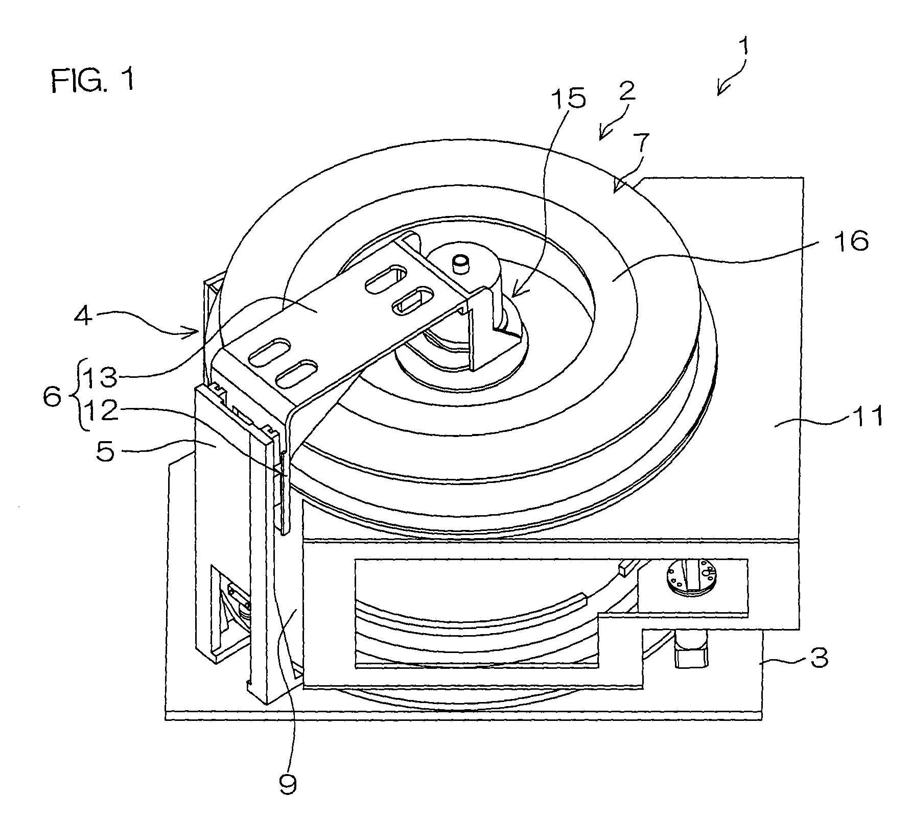
[0030]FIG. 1 is a perspective view showing the construction of a treatment unit 2 of a substrate treatment apparatus 1 according to one embodiment of the present invention.

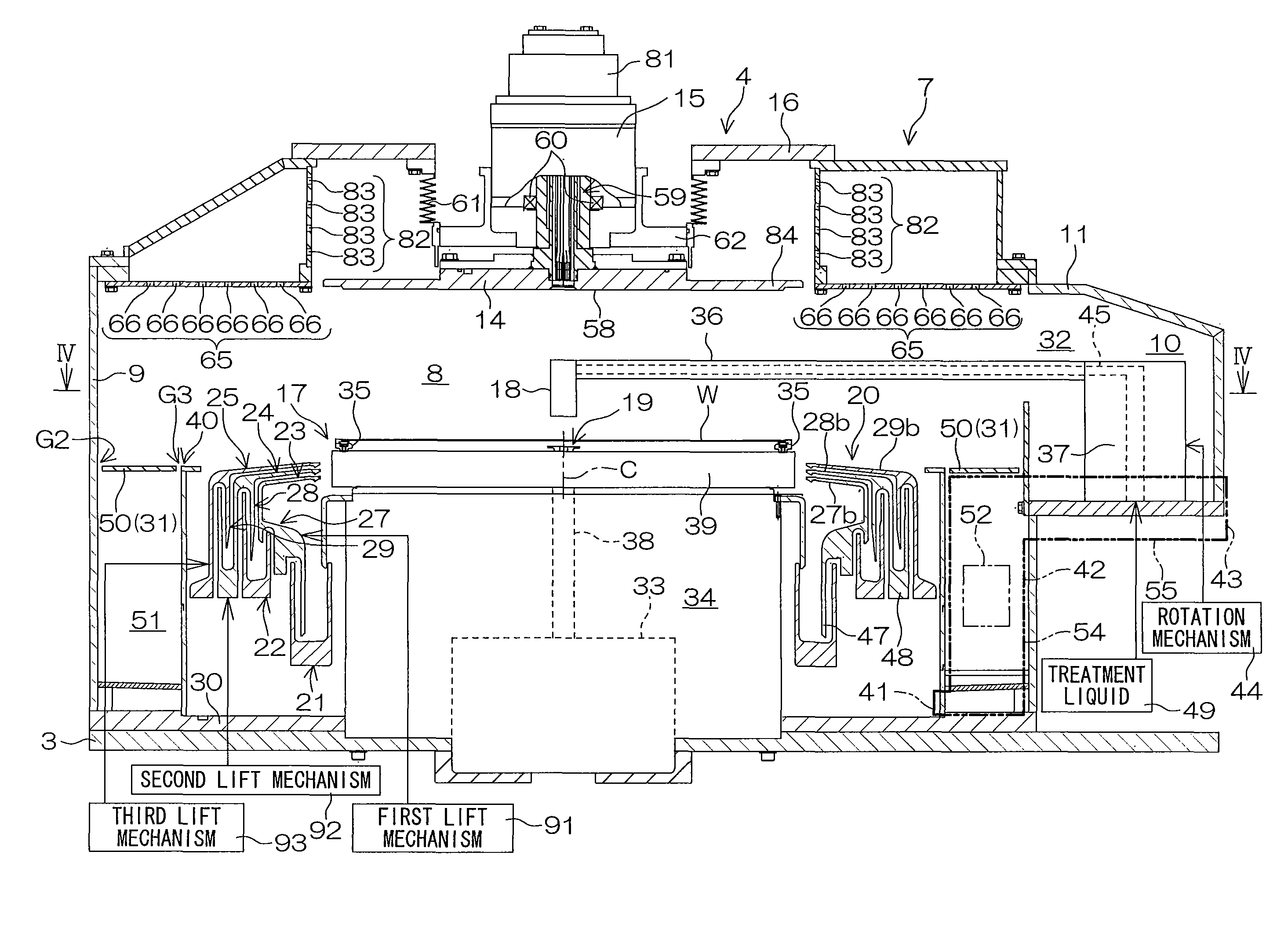
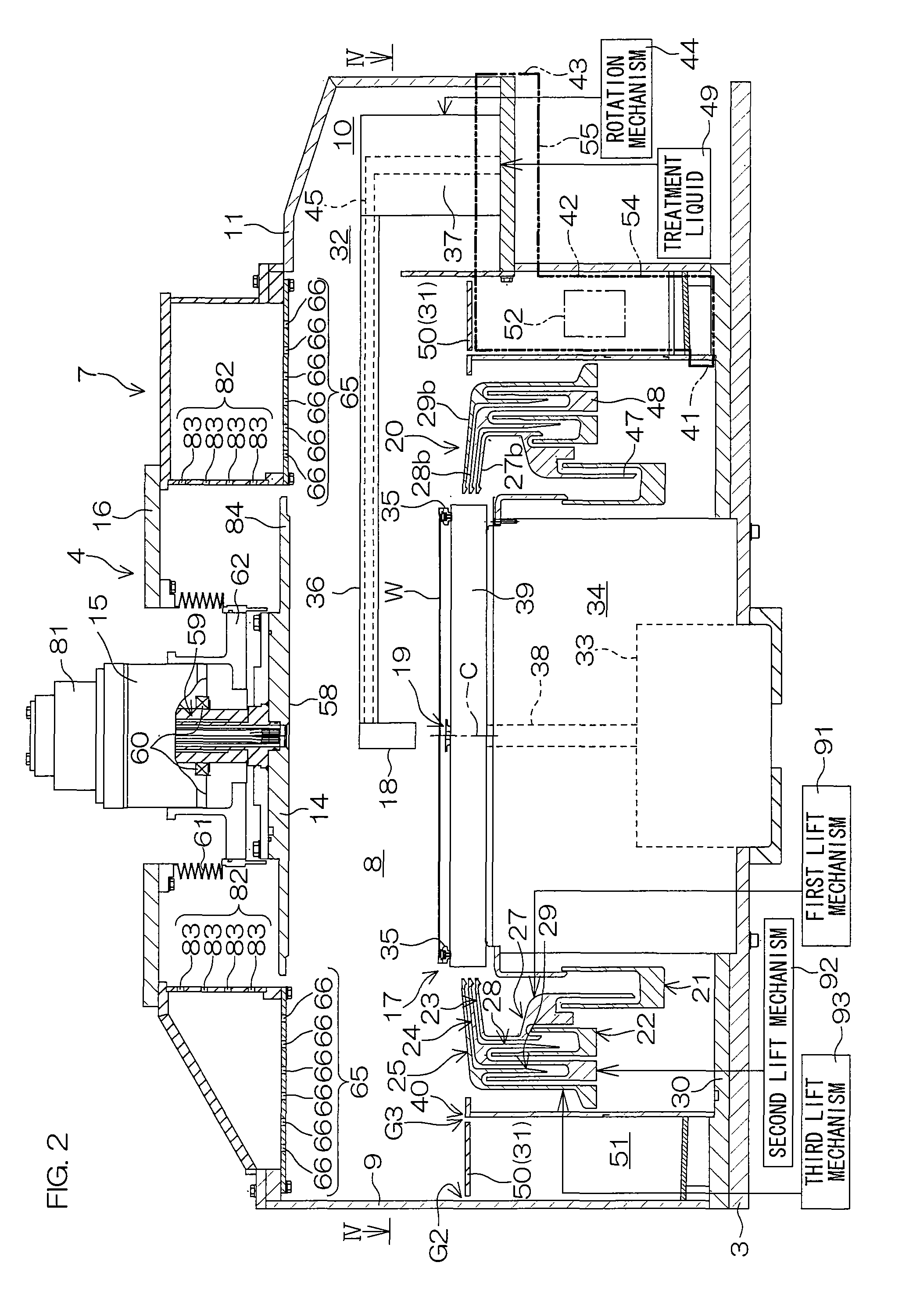
[0031]The substrate treatment apparatus 1 is of a single substrate treatment type adapted to treat a substrate W with a treatment liquid, and is installed in a clean room. The substrate treatment apparatus 1 includes a treatment unit 2. The treatment unit 2 includes a planar base 3, a treatment chamber 4 fixed onto the base 3, a post (shield member supporting member) 5 fixed onto the base 3 as extending vertically, a lift arm (lift unit) 6 extending generally horizontally above the treatment chamber 4 and movable up and down with respect to the post 5, and a gas supply unit (gas supply portion) 7 attached to an upper portion of the treatment chamber 4. The treatment chamber 4 includes a cylindrical partition wall 9 having a hollow cylindrical shape and defining a treatment area 8 (see FIGS. 2 and 3) in which the s...


PUM

PropertyMeasurementUnit
areaaaaaaaaaaa
diameteraaaaaaaaaa
outer diameteraaaaaaaaaa

Abstract

A substrate treatment apparatus includes: a treatment chamber in which a substrate is treated; a substrate holding unit which holds the substrate in the treatment chamber; a shield member disposed above the substrate holding unit and having an opposing surface to be brought into opposed relation to the substrate holding unit; and a gas supply portion which has a downward gas supply port having an annular shape to surround the shield member as seen in plan and is disposed on an upper portion of the treatment chamber for supplying a gas into the treatment chamber.

Description

BACKGROUND OF THE INVENTION[0001]1. Field of the Invention[0002]The present invention relates to a substrate treatment apparatus which treats a substrate such as a semiconductor wafer, a glass substrate for a liquid crystal display device, a substrate for a plasma display device, a substrate for a FED (Field Emission Display) device, a substrate for an optical disk, a substrate for a magnetic disk, a substrate for a magneto-optical disk, and a substrate for a photo mask.[0003]2. Description of Related Art[0004]In production processes for semiconductor devices and liquid crystal display devices, a substrate such as a semiconductor wafer or a glass substrate for a liquid crystal display panel is treated with a treatment liquid and a treatment gas. For example, a substrate treatment apparatus of a single substrate treatment type adapted to treat a single substrate at a time includes a spin chuck which horizontally holds and rotates the substrate, a nozzle which supplies the treatment l...

Claims


Application Information

Patent Timeline
Patent Type & Authority Patents(United States)
IPC IPC(8): B05C11/00C23C16/00H01L21/67
CPCH01L21/6719H01L21/67017H01L21/67126
Inventor HASHIMOTO, KOJI
Owner DAINIPPON SCREEN MTG CO LTD
Why Eureka
Try Eureka