Method and construction for ventilation of hydrogen gas

a technology for hydrogen gas and ventilation, applied in the direction of electrochemical generators, manufacturing tools, cell components, etc., can solve the problems of hydrogen blisters, difficult and complicated manufacturing of explosion bonded backplates, and reduce the strength of cathode-intermediate layer joints, so as to prevent the formation of hydrogen blisters

Inactive Publication Date: 2001-09-20
AKZO NOBEL CHEM INT BV
View PDF4 Cites 0 Cited by
  • Summary
  • Abstract
  • Description
  • Claims
  • Application Information

AI Technical Summary

Benefits of technology

[0022] The venting channels are capable of venting out hydrogen gas derived from recombined hydrogen atoms that have diffused into the construction via the second metallic layer. The venting channels prevent formation of hydrogen blisters at the interface surfaces between the second and the third metallic layers which otherwise would cause losses in strength in the construction or even cause the joint between the metallic layers to separate. The venting channels formed suitably have a diameter of from about 0.01 .mu.m to about 1000 .mu.m, preferably from about 0.1 .mu.m to about 10 .mu.m. Further, by the term "channel"; also pores, grooves, canals or other pathways are included.
[0030] According to a variation of this preferred embodiment, especially when the third metallic layer is selected from Fe, Ni, Cr or alloys thereof, a fourth layer is joined to the construction to further prevent hydrogen embrittlement of the first layer. The fourth metallic layer is joined to, and in between, the third and the first metallic layers. The fourth layer is suitably selected from Ag, Cu, Al or alloys thereof, preferably from Ag. The thickness of the fourth layer is suitably from about 0.2 to about 10 mm, preferably from about 0.4 to about 5 mm.
[0034] The bipolar electrode of the present invention will effectively enable venting of hydrogen gas at the interface, i.e. the joint, between the cathode, the mesh and the protecting intermediate layer, via the formed venting channels, thus preventing formation of hydrogen blisters .
[0037] According to still another preferred embodiment of a construction, a mesh is joined to, and in between, the first and second metallic layers of the construction as above described. The joined construction according to this embodiment can, when exposed to relatively low-concentrated hydrogen environments, effectively protect the first layer from hydrogen embrittlement as well as provide for venting of formed hydrogen gas in the interface zone between the first and the second metallic layers. The first metallic layer, being a hydrogen-sensitive metal, is suitably selected from Fe, steel or alloys thereof, preferably from steel. The second metallic layer, being resistent to hydrogen, is suitably selected from Fe, steel, Ni, Cr or alloys thereof, preferably from steel. The thickness of the first layer suitably is from about 1 to about 20 mm, preferably from about 1 to about 10 mm. The thickness of the second layer suitably is from about 2 to about 20 mm, preferably from about 2 to about 15 mm. The construction is preferably used in moderately exposed hydrogen environments, such as for cathodic protection, off-shore applications, and in petrochemical industry.

Problems solved by technology

This may lead to formation of hydrogen blisters which, in turn, will reduce the strength of the cathode-intermediate layer joint of the electrode assembly as a consequence of the increased pressure which may cause separation thereof.
In assemblies as described in U.S. Pat. No. 4,116,807, however, the explosion bonded backplates are difficult and complicated to manufacture due to the difficulties to distribute energy evenly on the surface on which the strips are placed.
The strips can therefore also be difficult to explosion bond at specific fixed points on the backplates.
Another drawback with this type of embodiments is that the connection area, which is unventilated, between the strips and the backplates must be considerably large to guarantee good strength and good electrical contact.
Further, these types of electrode constructions are only applicable to multimonopolar cells and cell lines, i.e. cells in which the backplates are placed between the cells.

Method used


Image

  • Method and construction for ventilation of hydrogen gas

Examples


example

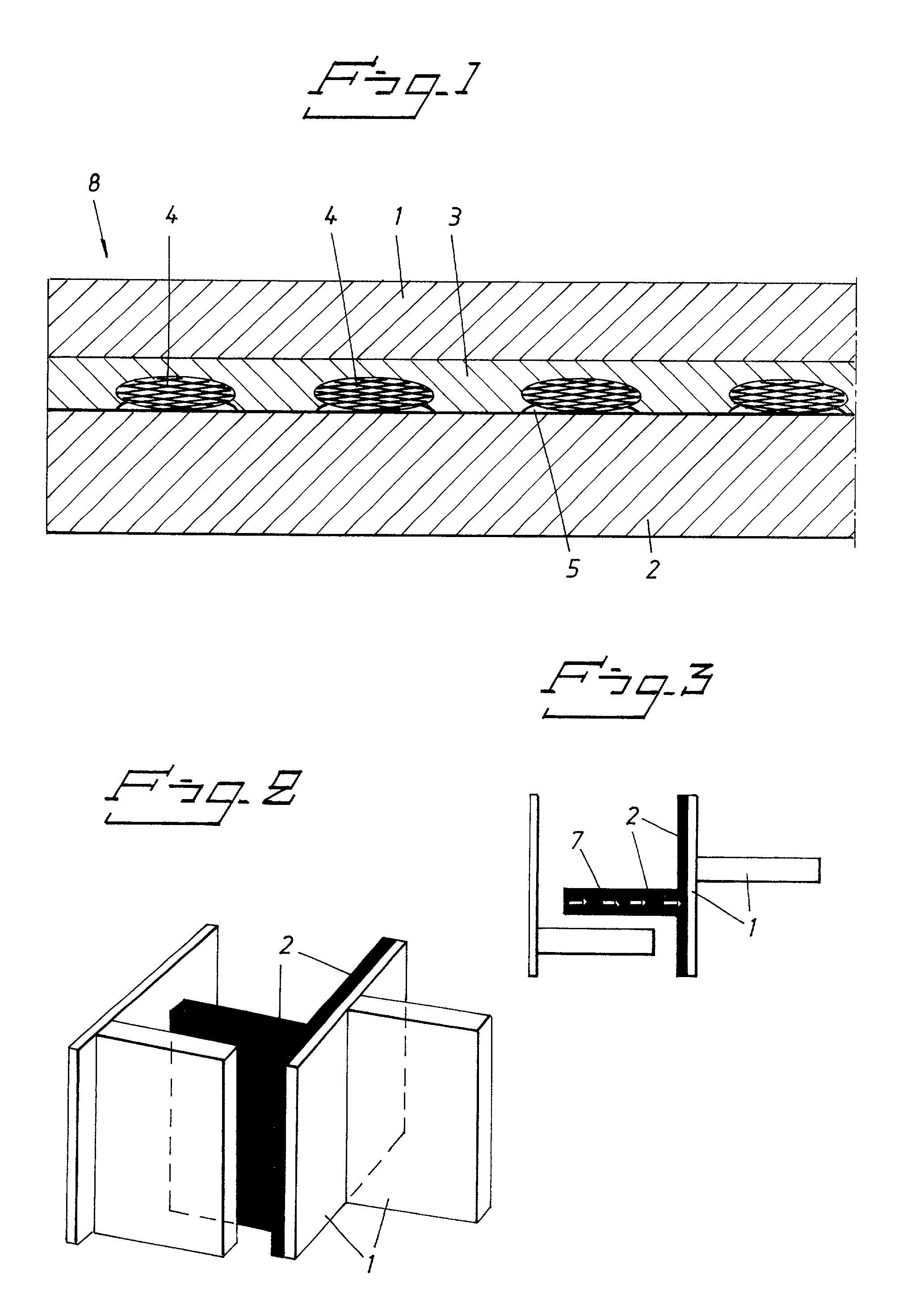
[0045] Structural strength of backplate samples, i.e. the joined steel (cathode), silver (intermediate layer) and titanium (anode) layers, were measured before and after electrolysis, for production of sodium chlorate, for explosion bonded conventional electrodes without mesh and electrodes provided with mesh according to FIG. 2 and 3. Explosion bonded samples were taken from different parts of the backplate to investigate the influence of poor bonding, which were analysed in small parts by ultrasonic analysis. The sample was 0.12 m.times.0.12 m.times.0.030 m of the backplate. The tests were run on the backplate samples in a four-unit chlorate cell. The temperature of the electrolyte was 65.degree. C. and the current density through the backplate was about 3-5 kA / m.sup.2.

[0046] In all the samples of the conventional electrodes, the structural strength after 10 days of electrolysis was lower than 1 MPa.

[0047] The samples provided with mesh maintained their original structural strengt...


PUM

PropertyMeasurementUnit
thicknessaaaaaaaaaa
diameteraaaaaaaaaa
thicknessaaaaaaaaaa

Abstract

The invention relates to a construction for ventilation of hydrogen gas comprising at least a first metallic layer (1), sensitive to hydrogen embrittlement, a second (2) metallic layer, and a mesh (4), wherein the first layer (1) is joined to the second layer (2), and said mesh (4), forming venting channels (5) through which channels (5) hydrogen can be vented, is joined to, and in between, said first (1) and second (2) metallic layers. The invention further concerns a method for production thereof.

Description

[0001] The present invention relates to a construction for ventilation of hydrogen gas and a method for production thereof. More specifically, the invention relates to a construction comprising at least a first and a second metallic layer joined together and a mesh joined to, and in between, said layers. The construction comprising the mesh imparts ventilation channels between the mesh and the layers thereby preventing formation of hydrogen blisters and reducing the hydrogen embrittlement of the first layer.[0002] Many metals used in constructions in contact with hydrogen are sensitive to hydrogen, e.g. such used in electrochemical cells for production of alkali metal chlorate. Various solutions have been proposed to overcome this problem.[0003] U.S. Pat. No. 3,992,279 discloses an electrode assembly comprising a Ti-based anode, a cathode, of an iron-based material, and an intermediate layer, of silver or gold, in between said anode and cathode. In an electrolytic cell, e.g. for pro...

Claims


Application Information

Patent Timeline
Patent Type & Authority Applications(United States)
IPC IPC(8): C25B1/02C25B9/04C25B11/02C25B11/12C01B3/02
CPCC25B9/04C25B11/02Y10T29/49117C25B9/65
Inventor HAKANSSON, BOFONTES, EDUARDODAVIDSSON, MAGNUSSUNDSTROM, HANS-GORANBLOMGREN, LARSCARLSSON, ARNE
Owner AKZO NOBEL CHEM INT BV
Why Eureka
Try Eureka