Apparatus with axis-parallel tension cables for ejecting a spin-stabilized body from a spacecraft

a technology of spin-stabilized space and ejection system, which is applied in the direction of cosmonautic components, cosmonautic parts, cosmonautic vehicles, etc., can solve the problems of compromising the operational reliability of the system, a relatively high weight, and a complex construction, so as to minimize the total mass and volume of the overall space flight system, reduce the weight and volume of the mechanism, and eliminate the effect of considerable safety risks

Inactive Publication Date: 2006-06-29
ASTRIUM GMBH
View PDF10 Cites 5 Cited by
  • Summary
  • Abstract
  • Description
  • Claims
  • Application Information

AI Technical Summary

Benefits of technology

[0013] In the inventive apparatus, the cable winding device cooperating with the cables serve to simultaneously impose the combined rotation and translation motion onto the flying body for spin-stabilizing and ejecting the flying body from an ejection tube or bay of the spacecraft, in which the apparatus is installed. Thereby, the spring-loaded winding device represents a very effective, simple, reliable, robust and safe drive mechanism for driving both the rotation and the translation motion for the ejection. To achieve this, the apparatus must first be set into a ready or loaded state, in which the two ring elements are axially spaced apart from one another, and the tension cables are paid out from the cable winding device and extend axis-parallel along a cylindrical contour between the two ring elements. Thereby, the torsion spring of the cable winding device is loaded or stressed, i.e. tensioned, and thus exerts a spring bias that tends to retract and wind-up the cables on the cable winding device.
[0016] The construction and operation of the apparatus according to the invention provides several advantages compared to conventional ejection apparatus. A very important advantage is the exclusion and avoidance of explosive devices or materials for ejecting the flying body, which thereby eliminates a considerable safety risk for the astronauts and for the spacecraft itself. Furthermore, the inventive apparatus minimizes the weight and volume of the mechanisms for achieving the spin-stabilization as well as the translational motion for the ejection, which thereby minimizes the total mass and volume of the overall space flight system. This in turn allows the available or usable payload mass and payload volume to be maximized. Still further, a reduction of the number of required mechanical and electrical functional components achieves a reduction of the complexity of the ejection mechanism, and therewith also an increase of the reliability and efficiency of the apparatus. When the cable winding device is preferably embodied as a cable spool or winch that is spring-loaded with a torsion spring as a drive element, the inventive apparatus does not need electrical energy for driving the ejection process. Thus, there is no need to provide high-current electrical supplies from the flying body to be ejected or from the spacecraft, so that any on-board electrical power supply system can be correspondingly simplified and reduced in capacity and weight. Also, the exact ratio or relationship between the rotation motion and the translation motion for the ejection can be selected simply by providing a suitable diameter of the cable winding spool or winch. In other words, a cable winding spool having a different diameter will provide a different ratio of rotation relative to translation for the ejection. The apparatus is thus easily adaptable to different ejection requirements.

Problems solved by technology

All of the above described conventional ejection systems have a substantial disadvantage of a relatively high weight and a complex construction.
This complexity leads to malfunctions or breakdowns that jeopardize the operational reliability of the systems.

Method used


Image

  • Apparatus with axis-parallel tension cables for ejecting a spin-stabilized body from a spacecraft
  • Apparatus with axis-parallel tension cables for ejecting a spin-stabilized body from a spacecraft
  • Apparatus with axis-parallel tension cables for ejecting a spin-stabilized body from a spacecraft

Examples


Embodiment Construction

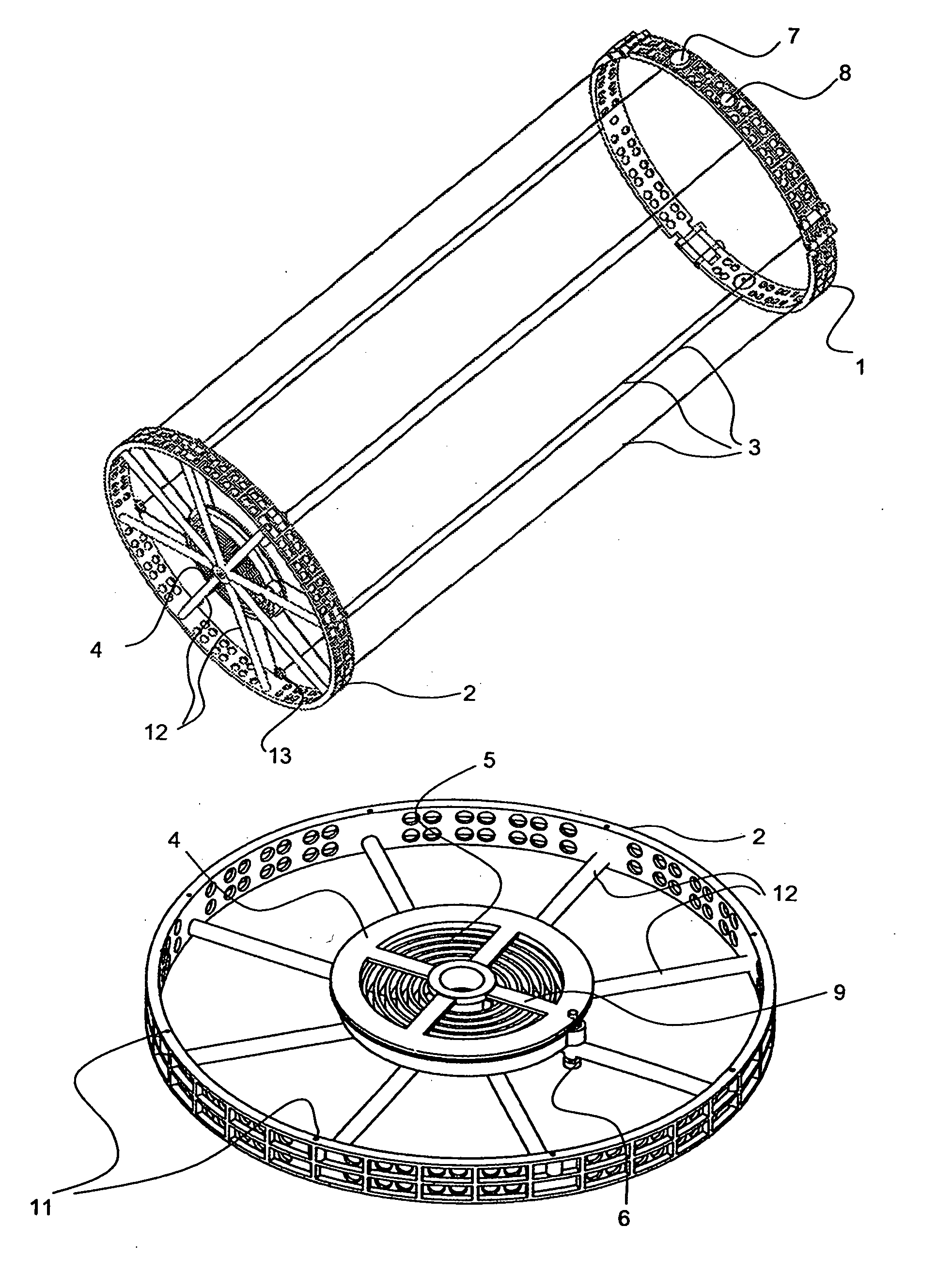
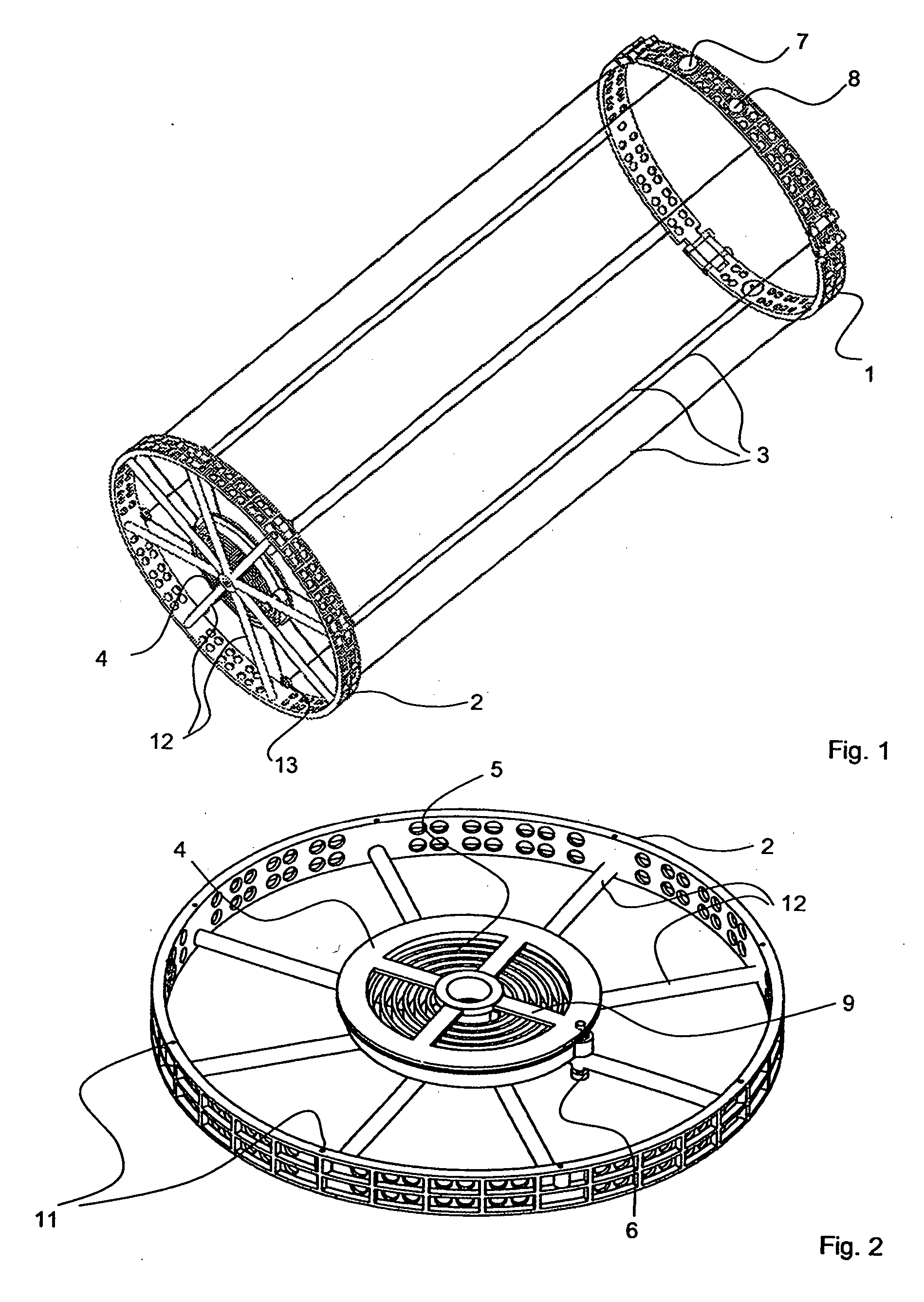
[0024]FIG. 1 shows an ejection apparatus according to an example embodiment of the invention. The ejection apparatus essentially comprises a first ring element 1, a second ring element 2, and a plurality of tension cables 3 extending between and interconnecting the two ring elements 1 and 2. In the present embodiment, the apparatus includes a total of eight such tension cables 3. The tension cables may be structurally embodied as any type of cable, rope, wire, fiber, or the like, of synthetic fiber materials or of metal or of other suitable materials, but are preferably embodied as metal wire cables, e.g. steel wire cables. The ring elements 1 and 2 may be constructed of metal, fiber reinforced composite material, or other suitable materials.

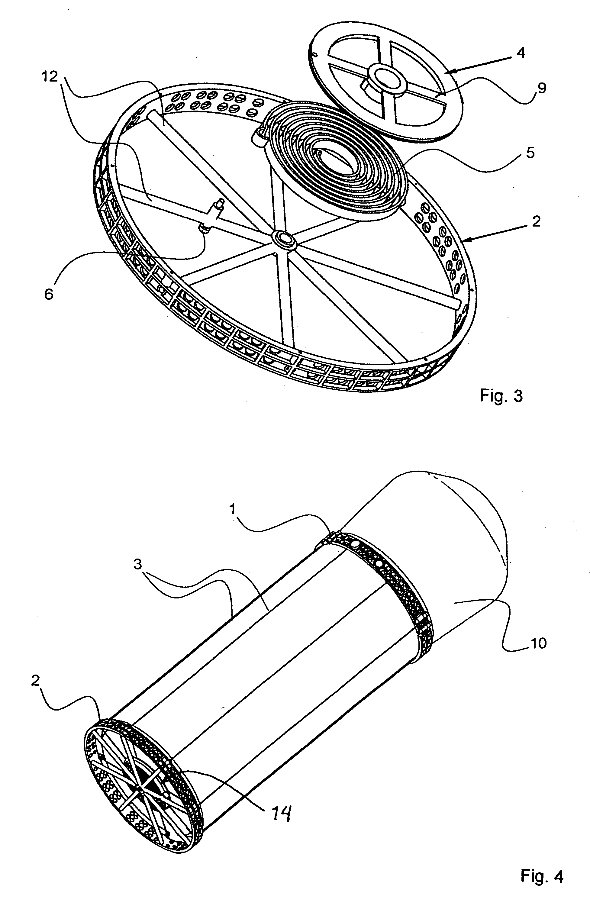
[0025] The apparatus further comprises a cable winding device 4 such as a cable winding spool, drum, winch, or the like. The cable winding device 4 is equipped with an internally arranged torsion spring 5 such as a coil spring or spiral spring,...


PUM


Abstract

An apparatus for ejecting a flying body (e.g. payload recovery container) from a spacecraft includes a first ring to be secured to the spacecraft, a cable winding device that is arranged on a second ring and that is releasably engageable with the flying body, and tension cables extending between the two rings. The cable winding device is spring-biased to wind-up the cables, which extend axis-parallel along the cylindrical outer shell of the flying body. Holding and guide elements on the first ring hold and guide the flying body. Catch elements on the cable winding device releasably engage receivers on the flying body. When the holding elements are released, the cables are retracted by the cable winding device, and the rotation of the cable winding device is transmitted to the flying body via the engaged catch elements and receivers. Thereby, the flying body is rotated and translationally ejected.

Description

CROSS-REFERENCE TO RELATED APPLICATION [0001] This application is related to the application entitled “Apparatus With Helical Tension Cables For Ejecting A Spin-Stabilized Body From A Spacecraft” by the same inventor and being filed on the same date as the present application. The entire disclosure of the related application is incorporated herein by reference. PRIORITY CLAIM [0002] This application is based on and claims the priority under 35 U.S.C. §119 of German Patent Application 10 2004 063 115.8, filed on Dec. 23, 2004, the entire disclosure of which is incorporated herein by reference. FIELD OF THE INVENTION [0003] The invention relates to an apparatus for ejecting a spin-stabilized space flying body from a spacecraft. The term space flying body covers any type of flying body capable of traveling in space, including spacecraft which may be propelled or unpropelled and manned or unmanned, and including containers such as payload return or retrieval containers, for example. BAC...

Claims


Application Information

Patent Timeline
Patent Type & Authority Applications(United States)
IPC IPC(8): B64G1/00
CPCB64G1/645
Inventor KOEHLER, HORST
Owner ASTRIUM GMBH
Why Eureka
Try Eureka