Cushioning clip

a technology of a clip and a shield, applied in the field of shields, can solve the problem of insufficient impact absorption effect, and achieve the effect of enhancing the capacity to absorb impa

Inactive Publication Date: 2009-07-28
DAIWA KASEI IND CO LTD
View PDF16 Cites 23 Cited by
  • Summary
  • Abstract
  • Description
  • Claims
  • Application Information

AI Technical Summary

Benefits of technology

[0007]According to a second aspect of the present invention, in the cushioning clip of the first aspect, the hollow part has formed therein an opening part opening towards the distal end side. Formation of this opening part in the hollow part produces an effect of making the cushioning part unlikely to be deformed upon application of a load from the movable member. In addition, the opening part in the hollow part produces an effect of enhancing the capacity to absorb an impact from the movable member.
[0008]According to a third aspect of the present invention, in the cushioning clip of the first or second aspect, the hollow part is provided with a projection part projecting from a base end side toward the distal end side. The provision of this projection part in the hollow part produces an effect of making the cushioning part more unlikely to be deformed upon the application of a load from the movable member.
[0009]The present invention can provide a cushioning clip having a cushioning part formed of a flexible material that is unlikely to be permanently deformed even when a long-term load or a load exceeding a certain limit is applied thereto.

Problems solved by technology

However, a sufficient impact absorbing effect cannot be obtained in receiving the movement of the movable member when the cushioning part is formed of a more rigid material.

Method used


Image

  • Cushioning clip
  • Cushioning clip
  • Cushioning clip

Examples


first embodiment

[0032]Hereinafter, a first embodiment mode of the present invention will be described in detail.

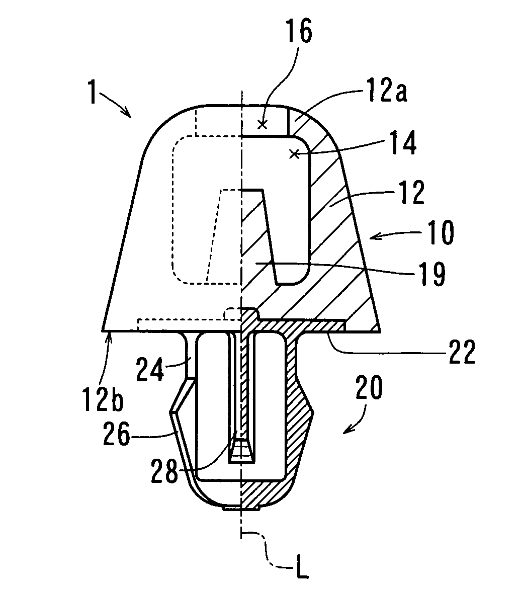
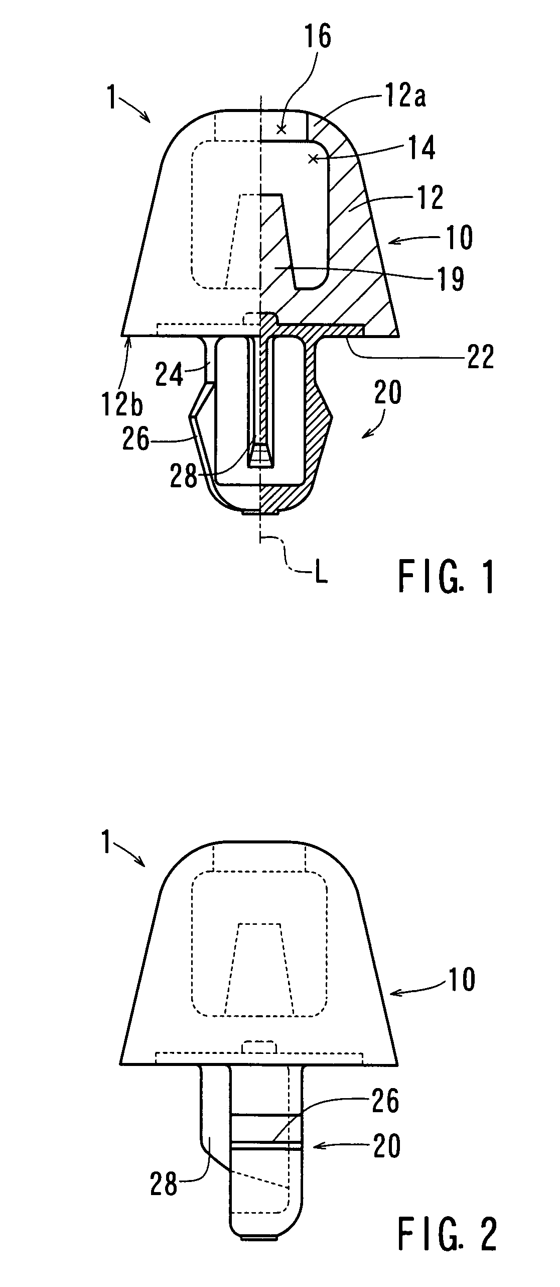
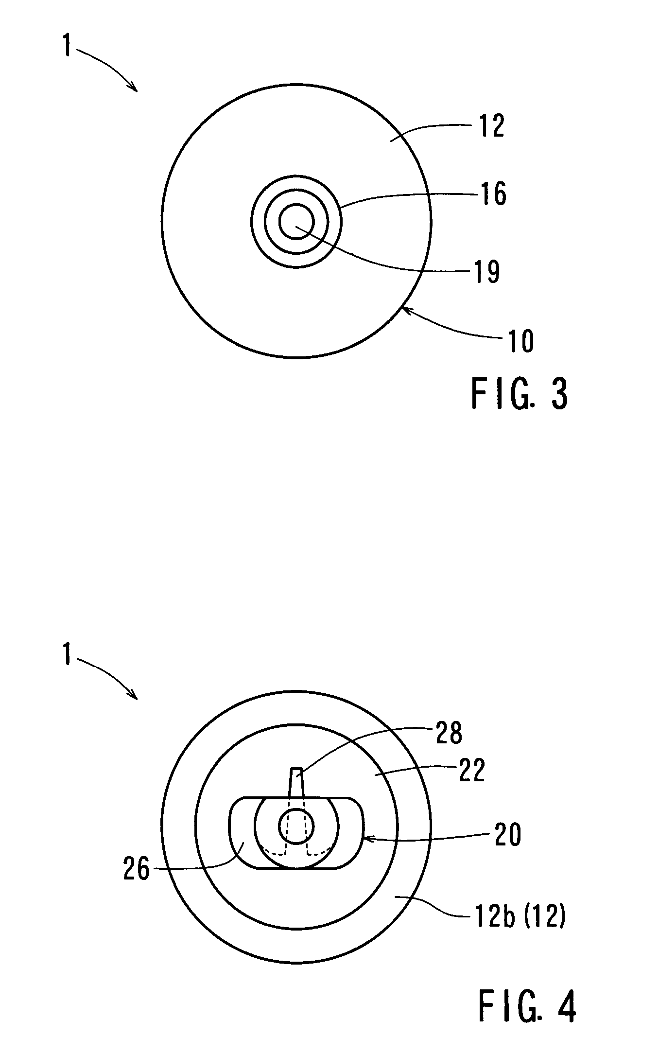
[0033]FIG. 1 is a front view illustrating a cushioning clip of the first embodiment mode, although it is shown in a sectional view on the right side of axis L. FIG. 2 is a side view illustrating the cushioning clip. FIG. 3 is a top view illustrating the cushioning clip. FIG. 4 is a bottom view illustrating the cushioning clip. FIG. 5 is a front view showing a state in which the cushioning clip is mounted to a stationary member. The cushioning clip 1, according to the first embodiment mode, is intended to absorb an impact force resulting from the opening or closing of a lid of a glove compartment located in front of a front passenger seat of an automobile. This cushioning clip 1 is broadly divided into a cushioning part 10 formed of a flexible material such as an elastomer resin, and a mounting part 20 formed of a rigid material such as polypropylene (PP). In this specification, a distal e...

second embodiment

[0057]Hereinafter, a second embodiment mode of the present invention will be described in detail.

[0058]In this embodiment, a cushioning clip is provided for receiving the movement of a movable member approaching a stationary member, at a position close to an end of the cushioning clip. The cushioning clip includes a cushioning part for absorbing an impact force and an engaging part coupled to the stationary member in which the cushioning part has a hollow part formed therein.

[0059]In the cushioning clip of this embodiment the hollow part can be formed so as to extend through in a direction perpendicular to an axis connecting an impact force receiving part of the cushioning part to the engaging part substantially in a region close to a center of the cushioning part.

[0060]Furthermore, in the cushioning clip of this embodiment the hollow part may include a projection part extending along the axis. In the cushioning clip of the second embodiment the hollow part can be formed along an ax...

third embodiment

[0070]A third embodiment mode of the present invention will be described hereinafter.

[0071]FIG. 13 is a front view, partially in section, of a cushioning clip of the third embodiment mode. FIG. 14 is a sectional view of the cushioning clip taken along a direction indicated by arrows B in FIG. 13. The cushioning clip 301 shown in these figures is intended to absorb an impact force caused upon the opening and closing of a glove compartment in a cabin of an automobile. The cushioning clip 301 is broadly divided into a cushioning part 340, formed of a flexible material such as elastomer resin, and an engaging part 320, formed of a rigid material such as polypropylene (PP). Apart from minor differences in the location of engaging claws 326 on the leg part 324 and the shape of a rib 328, the engaging part 320 is structurally identical with that of the second embodiment mode.

[0072]The cushioning part 340 assumes the shape of a truncated cone as a whole and receives an impact force on a sma...


PUM


Abstract

A cushioning clip for receiving a movement of a movable member approaching a stationary member, including a cushioning part, for absorbing an impact force, and a mounting part for mounting the cushioning part to the stationary member. The cushioning part is formed of a flexible material exhibiting elasticity. The mounting part is formed of a rigid material exhibiting a predetermined rigidity. A hollow part is formed in the cushioning part. An inner wall of the hollow part is formed almost perpendicularly to the stationary member, and an apex part on a distal end side of the inner wall is flexed inwardly.

Description

[0001]This is a continuation of International Patent Application PCT / JP05 / 020361, filed Nov. 7, 2005, which claims priority of Japanese Patent Application S.N. 2004-342551 filed Nov. 26, 2004.FIELD OF THE INVENTION[0002]The present invention relates to a cushioning clip for receiving the movement of a movable member for use in various opening and closing components of an automobile for example. The cushioning clip may be at a location close to an end of the movable member and able to absorb an impact force of the movable member.BACKGROUND OF THE INVENTION[0003]Conventionally known as a cushioning clip, this kind of clip is disclosed in JP 2003-202043 A for example. This cushioning clip is composed of a cushioning part, for receiving the movement of a movable member approaching a stationary member at a location close to an end of the movable member, and a mounting part, for mounting the cushioning part to a predetermined location of the stationary member. Since the cushioning part is...

Claims


Application Information

Patent Timeline
Patent Type & Authority Patents(United States)
IPC IPC(8): B60R19/00
CPCE05F5/022F16F1/373F16F1/44F16B21/086E05Y2600/53E05Y2900/538E05Y2900/546Y10T24/309F16F2230/007F16F7/00B60J5/10
Inventor AOYAMA, TETSUYA
Owner DAIWA KASEI IND CO LTD
Why Eureka
Try Eureka