Aircraft LED dome light having rotatably releasable housing mounted within mounting flange

a technology of led dome lights and housings, which is applied in the field of general illumination, can solve the problems of not providing enough ambient light to clearly illuminate the floor and aisle, large gaps between the lights, and the inability to add more leds to a conventional dome light, so as to reduce the amount of heat produced and minimize the size and weight of the housing

Inactive Publication Date: 2009-07-28
BE AEROSPACE INCORPORATED
View PDF55 Cites 127 Cited by
  • Summary
  • Abstract
  • Description
  • Claims
  • Application Information

AI Technical Summary

Benefits of technology

[0003]The invention is generally directed to a light fixture and method of providing ambient lighting suitable for use in an aircraft cabin. The light fixture utilizes light emitting diodes (LEDs) and a reflector to generate bright but diffuse light. The combination of LEDs and the reflector allows a very small number of LEDs to be used to provide light that is bright enough for a passenger to see relatively large areas clearly, but is diffuse enough that a passenger can comfortably look into the light. The small number of LEDs allows the lighting fixture housing size and weight to be minimized, and decreases the amount of heat produced by the light fixture.

Problems solved by technology

Problems exist, however, with these conventional lights, because when they are mounted in the ceiling, they do not provide enough ambient light to clearly illuminate the floor and aisle.
This leaves large gaps of dimly lit areas between the lights.
Adding more LEDs to a conventional dome light is not desirable because the additional LEDs not only increase the amount of heat generated by the light fixture and increase the size of the light fixture, but also result in light that is too bright for passengers to comfortably look into.

Method used


Image

  • Aircraft LED dome light having rotatably releasable housing mounted within mounting flange
  • Aircraft LED dome light having rotatably releasable housing mounted within mounting flange
  • Aircraft LED dome light having rotatably releasable housing mounted within mounting flange

Examples


Embodiment Construction

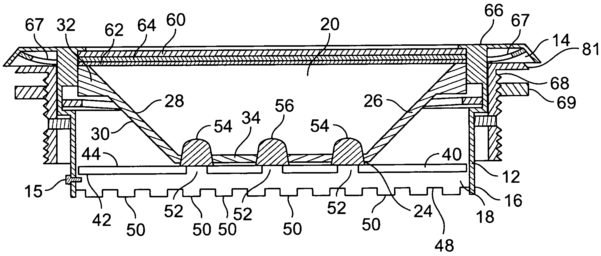
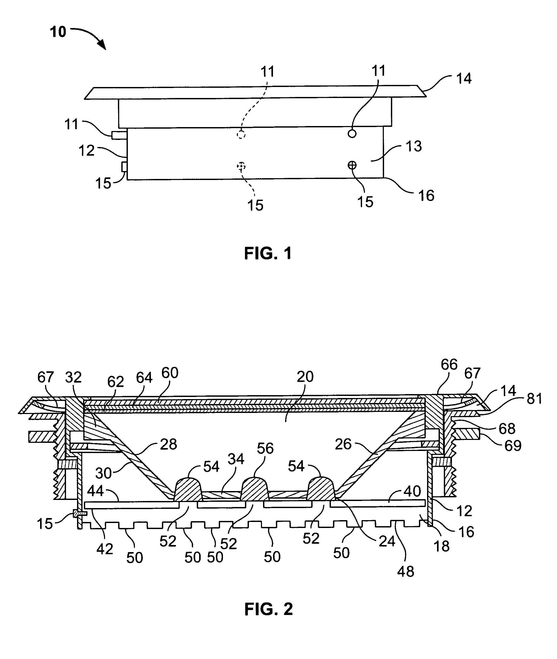
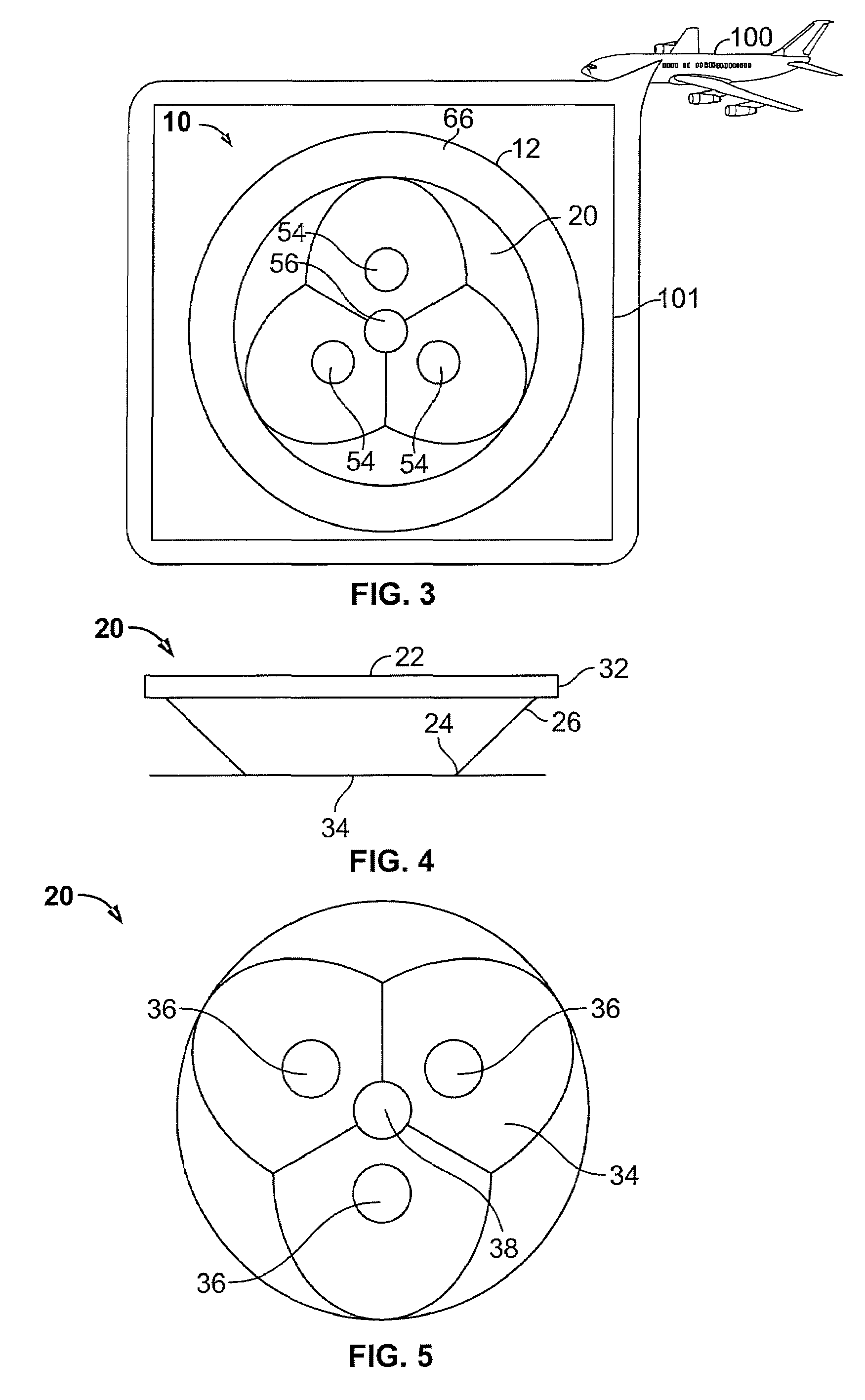
[0013]The invention is generally directed to a light fixture for use in an LED lighting system for an aircraft or other transportation vehicle. Referring to FIGS. 1-3, an embodiment of the light fixture, generally labeled 10, includes a housing 12 having a first end 14 and a second end 16. The housing includes a housing rim 66 adjacent to the first end 14. The housing may have a substantially cylindrical shape as depicted in the embodiment in FIGS. 1-3, however the housing is not limited to a cylindrical shape and in other embodiments of the invention the housing may be another shape. The second end 16 is attached to a base plate 18. The housing 12 defines a passageway between the first end 14 and the second end 16 and has an exterior housing surface 13. A pin 11 extends from the exterior housing surface 13. The embodiment in FIG. 1 may have three pins 11. A different number of pins may be used in other embodiments. The housing 12 may be constructed of any suitable material includin...


PUM


Abstract

A lighting fixture for providing illumination comprising a housing, a printed circuit board, and a plurality LEDs connected to the printed circuit board. Optionally an emergency LED may also be included. A heat sink is connected to the housing and printed circuit board. Each of the plurality of the LEDs is mounted on the heat sink. A reflector is disposed inside the housing such that the light from the LEDs is mixed together and projected out of the illumination end of the housing by the surface of the reflector. The lighting fixture is received into a mounting flange assembly. A method for providing illumination using the above.

Description

FIELD OF THE INVENTION[0001]This invention pertains to general illumination, specifically to providing light from LEDs for use on business jets, commercial aircraft and other transportation vehicles.BACKGROUND OF THE INVENTION[0002]Conventional methods and devices for providing lighting are generally known. For instance, dome lights are installed in business jets and commercial aircraft to allow passengers to see the aisles, door handles and signs. Conventional dome lights utilize arrays of 5 mm LEDs to provide illumination. Problems exist, however, with these conventional lights, because when they are mounted in the ceiling, they do not provide enough ambient light to clearly illuminate the floor and aisle. Instead, in a manner similar to spotlights, only the area directly in front of them is illuminated. This leaves large gaps of dimly lit areas between the lights. Adding more LEDs to a conventional dome light is not desirable because the additional LEDs not only increase the amou...

Claims


Application Information

Patent Timeline
Patent Type & Authority Patents(United States)
IPC IPC(8): F21S8/10
CPCB60Q3/025B60Q3/0256B60Q3/0259F21V29/70B64C2027/8236F21V29/004F21W2101/06F21W2101/08F21Y2101/02B64D2011/0038F21Y2115/10B60Q3/43B60Q3/46B60Q3/47B64D2203/00F21W2107/30F21W2106/00
Inventor GLOISTEN, JENNIFER L.REISFELD, FREDERICKZENG, SAMUEL
Owner BE AEROSPACE INCORPORATED
Why Eureka
Try Eureka