Supercharge Your Innovation With Domain-Expert AI Agents!

Systems and methods for creating MEMS gyros

a technology of system and method, applied in the direction of microstructural devices, turn-sensitive devices, instruments, etc., can solve the problems of loss of yield of usable mems gyros per wafer, deviating out of place, and subtle differences in the angle of some structural components of mems gyros, and achieve the effect of higher yield of usable mems gyros

Inactive Publication Date: 2009-07-28
HONEYWELL INT INC
View PDF2 Cites 0 Cited by
  • Summary
  • Abstract
  • Description
  • Claims
  • Application Information

AI Technical Summary

Problems solved by technology

Current methods for producing Micro Electro Mechanical System (MEMS) gyros using Deep Reactive Ion Etching (DRIE) technology result in subtle differences in the angle of some structural components of MEMS gyros.
For example, if the angle of a flexure is not completely perpendicular to the plane of a MEMS gyro device, it will deviate out of place creating an error source when it is driven to oscillation.
If this motor bias exceeds specified limits, it results in a loss of yield of the number of usable MEMS gyros per wafer.

Method used


Image

  • Systems and methods for creating MEMS gyros
  • Systems and methods for creating MEMS gyros
  • Systems and methods for creating MEMS gyros

Examples


Embodiment Construction

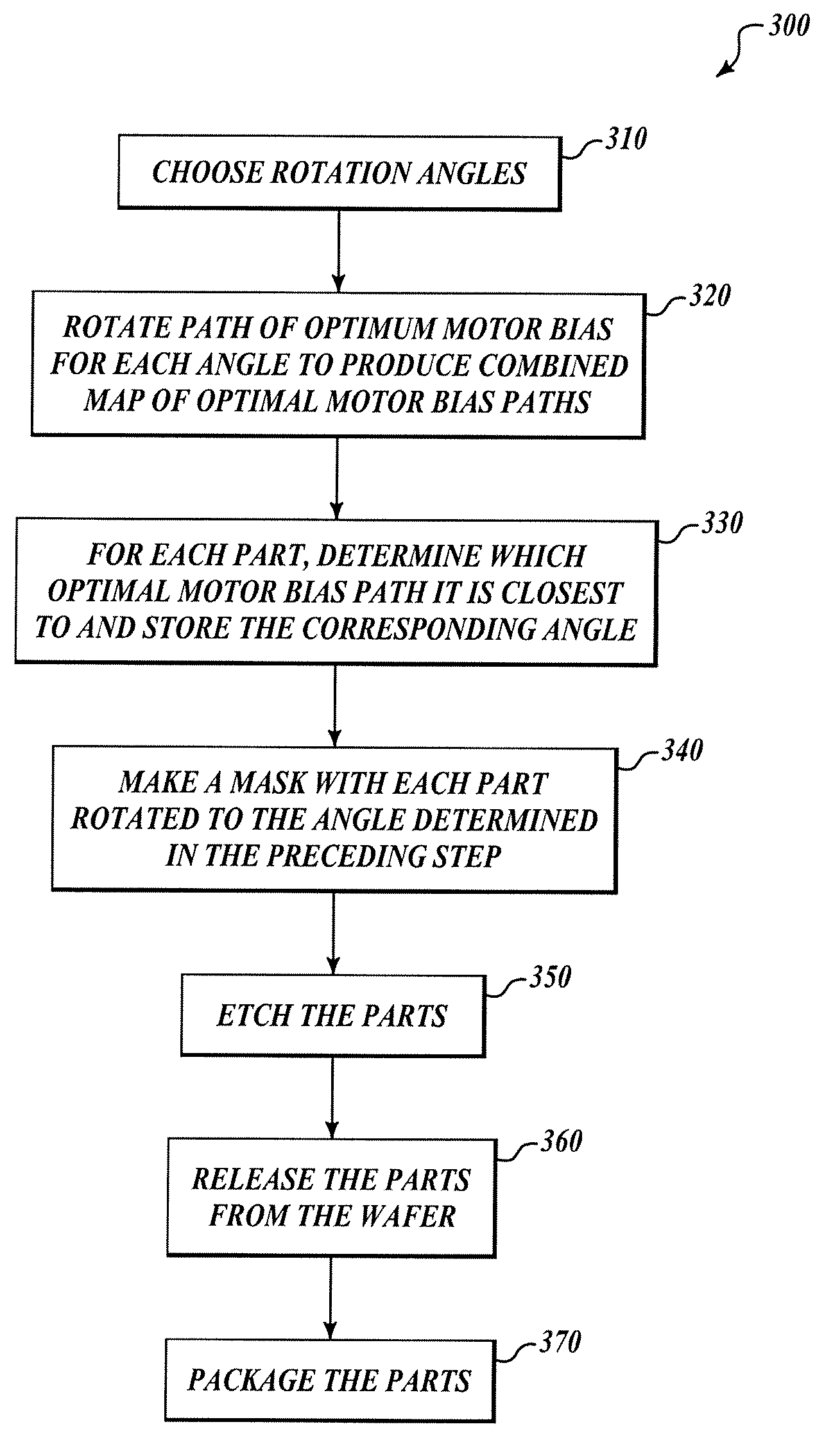
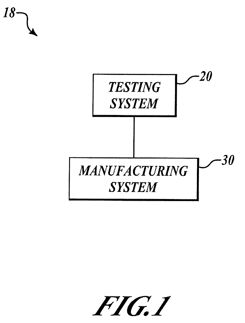
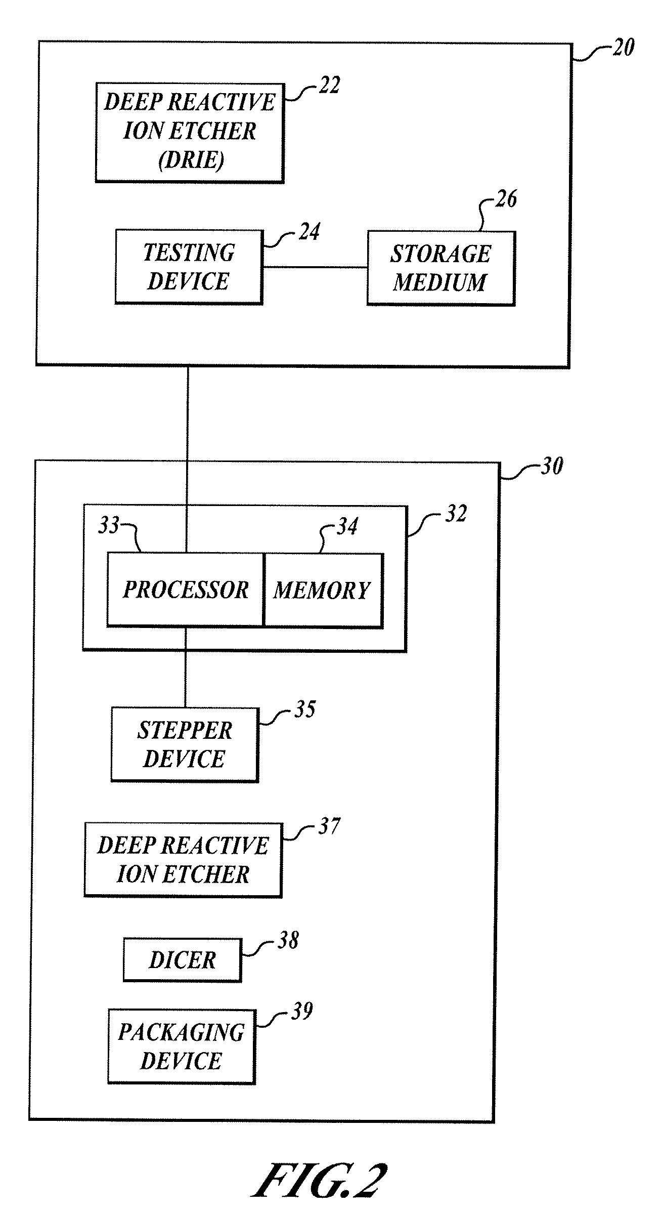
[0013]FIG. 1 illustrates a schematic view of an example system 18. In one embodiment, the system 18 includes a testing system 20 and a manufacturing system 30. The testing system 20 is configured to produce a map of motor bias for a given deep reactive ion etching (DRIE) device. The manufacturing system 30 uses the map of motor bias to produce an optimal path of motor bias for the DRIE device across a wafer. This optimal path is then rotated by one or more angles to produce additional optimal paths of motor bias that are related to the angle by which the initial optimal path of motor bias was rotated. The manufacturing system 30 is also configured to determine the best orientation for each gyro to be created on a wafer by determining the closest optimal path of motor bias in relation to each gyro on the wafer. The manufacturing system 30 is further configured to create MEMS gyros based on the determined orientation. The system 30 may include a gyro generating device that in some emb...


PUM


Abstract

Methods and systems for creating microelectromechanical system (MEMS) gyros. The methods and systems include generating a map of motor bias and creating MEMS gyros based on the map of motor bias to achieve a higher yield of usable MEMS gyros per wafer. The systems include a processor with components configured to determine paths of optimal motor bias for a given deep reactive ion etcher on a wafer, a stepper for imprinting a pattern for each gyro in an orientation that corresponds to the path of optimal motor bias each gyro is calculated to be most near on the wafer, and a deep reactive ion etcher to etch the gyros in the wafer.

Description

BACKGROUND OF THE INVENTION[0001]Current methods for producing Micro Electro Mechanical System (MEMS) gyros using Deep Reactive Ion Etching (DRIE) technology result in subtle differences in the angle of some structural components of MEMS gyros. For example, if the angle of a flexure is not completely perpendicular to the plane of a MEMS gyro device, it will deviate out of place creating an error source when it is driven to oscillation. These differences are distributed across each wafer in a reproducible pattern for particular DRIE devices. The subtle differences are referred to in this application as motor bias. If this motor bias exceeds specified limits, it results in a loss of yield of the number of usable MEMS gyros per wafer.[0002]Thus, there is a need for reducing the effect of motor bias in the creation of MEMS gyros and creating a higher yield per wafer.BRIEF SUMMARY OF THE INVENTION[0003]The present invention comprises methods and systems for creating microelectromechanica...

Claims


Application Information

Patent Timeline
Patent Type & Authority Patents(United States)
IPC IPC(8): H01L21/00B81C99/00G01C19/56
CPCG01C25/00G01C19/56
Inventor DWYER, PAUL W.COUSSEAU, PETER L.
Owner HONEYWELL INT INC
Features
  • R&D
  • Intellectual Property
  • Life Sciences
  • Materials
  • Tech Scout
  • Unparalleled Data Quality
  • Higher Quality Content
  • 60% Fewer Hallucinations
Learn More