Diagnostic method and apparatus for a pressurized gas supply system

a technology of pressure gas supply system and diagnostic method, which is applied in the direction of container filling under pressure, liquid handling, packaging goods type, etc., can solve the problems of unsatisfactory long period of time for filling the vessel or tank, and achieve the effect of preventing either an excessively fast or excessively slow fill rate, preventing an excessive pressure rise, and preventing an excessively fast fill ra

Active Publication Date: 2009-08-04
AIR PROD & CHEM INC
View PDF22 Cites 87 Cited by
  • Summary
  • Abstract
  • Description
  • Claims
  • Application Information

AI Technical Summary

Benefits of technology

[0012]In accordance with both the method and apparatus of this invention information available from a pressurized-gas supply system is employed to prevent either an excessively fast or excessively slow fill rate to a receiving tank, without the use of feedback instrumentation on the receiving tank. It is extremely important to prevent an excessively fast fill rate, which is reflected by an undesirably high gas pressure in the vessel; creating a dangerous overheating condition. It is of less concern if the fill rate is too slow. If the fill rate is too slow, it can take an undesirably long period of time to fill the vessel or tank, which although undesirable will not damage the system or otherwise create an unsafe condition. Thus, in accordance with the broadest aspects of this invention the apparatus and method utilizes information available from a pressurized-gas supply system to prevent an excessive pressure rise in the receiving tank; thereby preventing a potentially dangerous overheating problem.

Problems solved by technology

If the fill rate is too slow, it can take an undesirably long period of time to fill the vessel or tank, which although undesirable will not damage the system or otherwise create an unsafe condition.

Method used


Image

  • Diagnostic method and apparatus for a pressurized gas supply system
  • Diagnostic method and apparatus for a pressurized gas supply system
  • Diagnostic method and apparatus for a pressurized gas supply system

Examples


Embodiment Construction

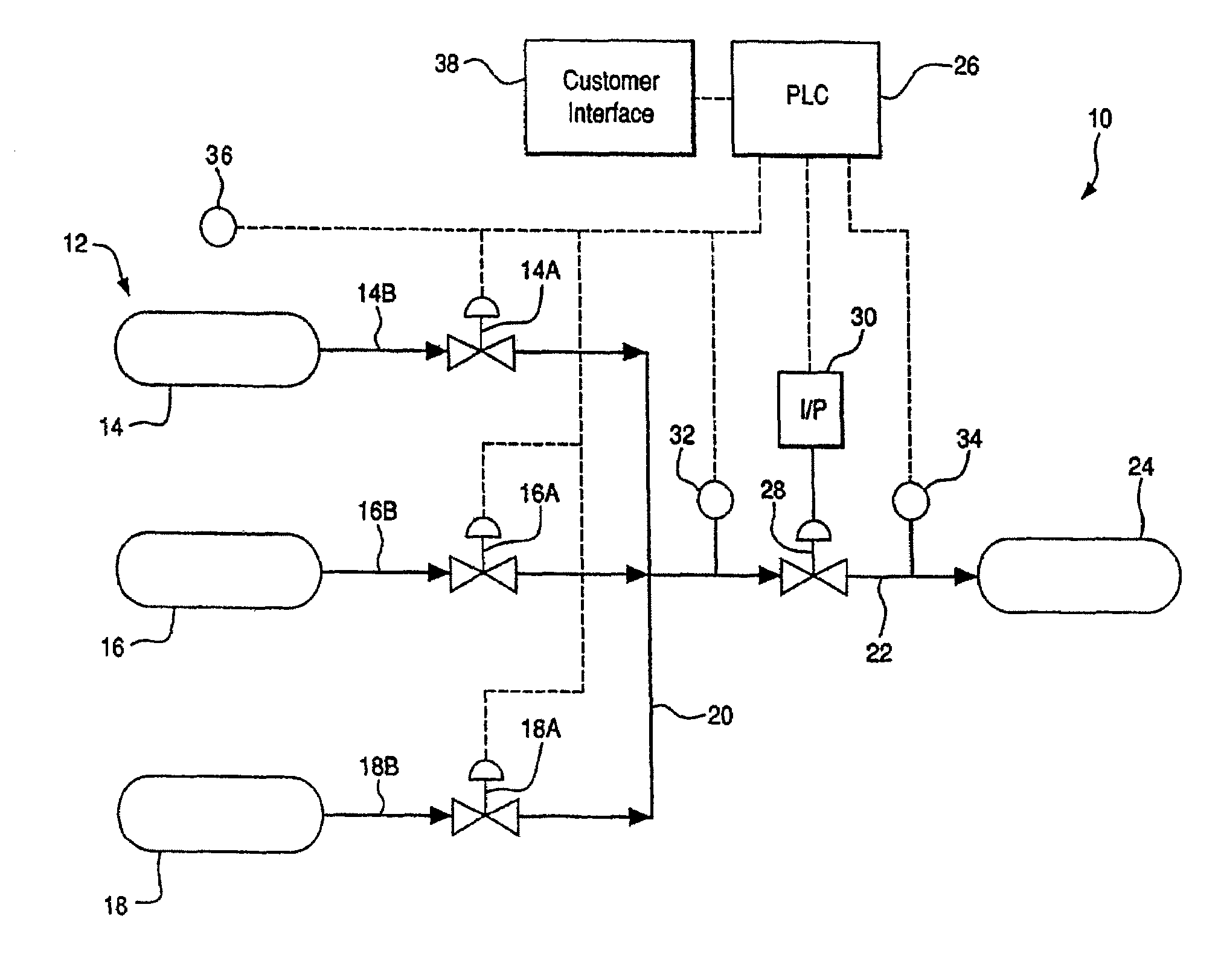
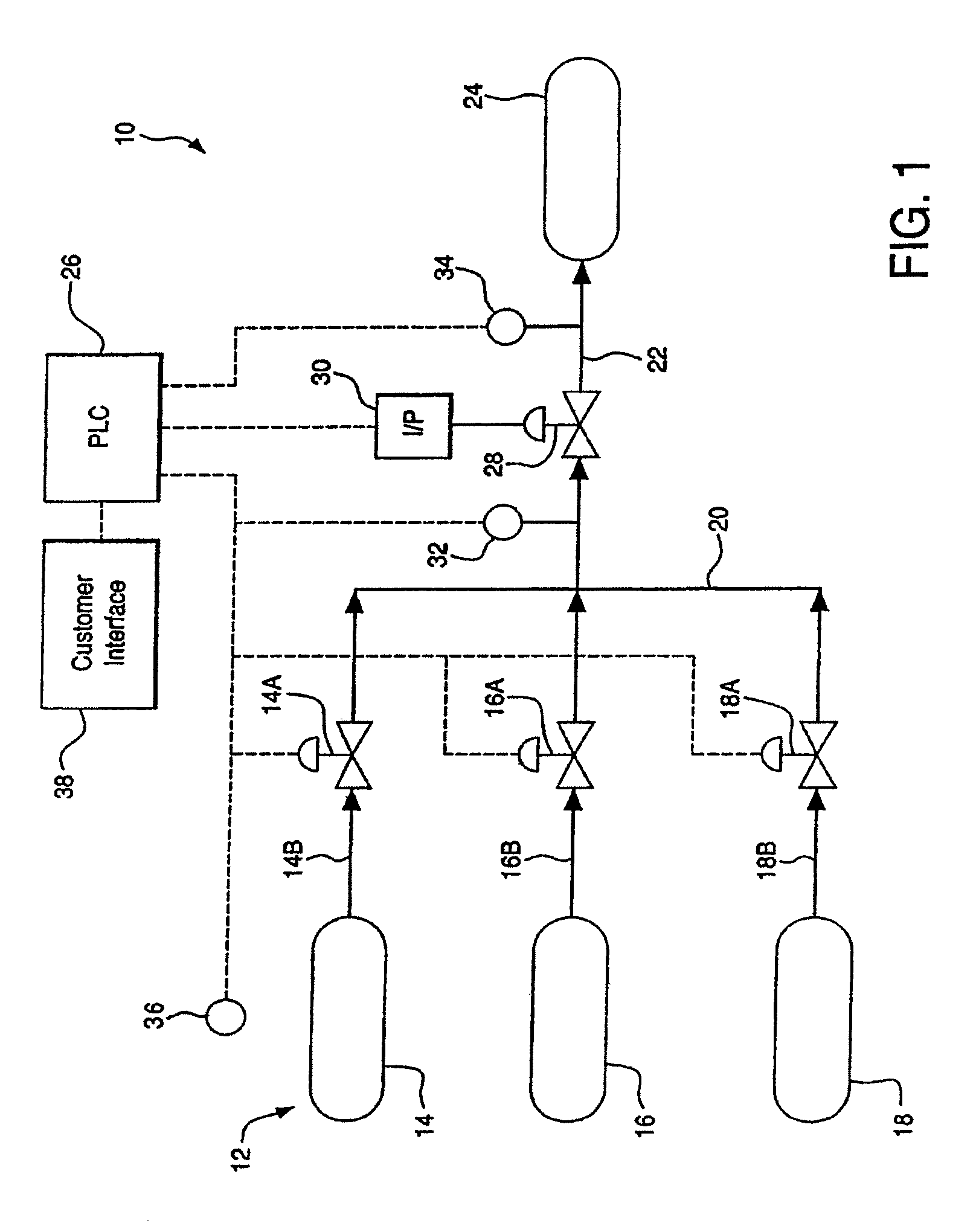
[0041]Referring to FIG. 1, a representative pressurized gas supply system employing the self-diagnostic features of the present invention is illustrated at 10. It should be understood that the specific arrangement of the pressurized gas supply system can be varied within wide limits. The only requirement is that it employ the self-diagnostic feedback system to be described in connection with the pressurized gas supply system 10.

[0042]Still referring to FIG. 1, the pressurized gas supply system 10 includes a storage section 12, which, as illustrated, includes three, equal-sized, compressed gas storage vessels 14, 16 and 18. It should be understood that the self-diagnostic features to be described hereinafter can be employed in a pressurized gas supply system including more or less than three storage vessels. Moreover, the storage vessels can be of different volumes, and one or more storage vessels can be cascaded together under the control of a single control valve. In addition, the ...


PUM

PropertyMeasurementUnit
timeaaaaaaaaaa
pressureaaaaaaaaaa
pressuresaaaaaaaaaa

Abstract

A diagnostic method for a gas supply system includes: determining a desired ramp rate for filling a vessel from a supply of compressed gas; monitoring the actual pressure of gas entering the vessel; and discontinuing the flow of gas into the vessel when the actual pressure deviates from the intended pressure at the desired ramp rate by an undesired amount. A system for carrying out the method includes a flow controller for controlling operation of the supply system to deliver compressed gas from a source to a vessel through a supply line at a desired ramp rate. The system employs a pressure monitor downstream of a control valve for measuring the pressure of gas directed into the vessel and transmitting pressure-related data to the flow controller, which closes the control valve to discontinue filling of the vessel if the actual pressure exceeds a permissible deviation from the intended pressure.

Description

BACKGROUND OF THE INVENTION[0001]This invention relates generally to a system for delivering compressed gas to a receiving tank or vessel and more specifically to a diagnostic method and apparatus for shutting off the gas supply to the vessel if, during the fill cycle, the pressure of the gas in the vessel deviates by an undesired amount from the intended pressure at a desired ramp rate (i.e., desired pressure increase in the fueling hose or line per unit time during the fill cycle). The desire ramp rate directly relates to the desired fill rate.[0002]Numerous supply systems employed to fill a receiving tank or vessel with compressed gas are known in the art. These systems include cascade filling processes and systems that employ multiple high-pressure storage vessels to charge a lower pressure-receiving vessel or tank, as exemplified in Borck U.S. Pat. No. 6,779,568. The '568 patent discloses that, for a constant filling time, the peak temperature of the gas in the receiving tank w...

Claims


Application Information

Patent Timeline
Patent Type & Authority Patents(United States)
IPC IPC(8): B65B57/00
CPCF17C5/06Y02E60/321F17C2270/0178F17C2250/0673F17C2201/0109F17C2201/056F17C2201/058F17C2205/0142F17C2205/0323F17C2205/0338F17C2221/012F17C2221/017F17C2223/0123F17C2223/035F17C2223/036F17C2227/043F17C2250/032F17C2250/043F17C2250/0636F17C2260/023F17C2270/0168Y02E60/32
Inventor FARESE, DAVID JOHNCARLSON, TODD ERICCOHEN, JOSEPH PERRYWITMER, AMANDA ELIZABETHSCHULTZ, KEITH H.
Owner AIR PROD & CHEM INC
Why Eureka
Try Eureka