Vapor recovery control valve

a technology of flow control valve and vapor recovery, which is applied in the direction of functional valve types, machines/engines, combustion air/fuel air treatment, etc., can solve the problems of pressure drop within, pressure increase within the tank, pressure drop within, etc., and achieve the effect of preventing pressure drop within the tank

Active Publication Date: 2012-05-15
RAVAL - AGRI COOP SOCIETIES
View PDF19 Cites 2 Cited by
  • Summary
  • Abstract
  • Description
  • Claims
  • Application Information

AI Technical Summary

Benefits of technology

[0014]Venting the fuel tank under the regular course of operation, so as to prevent excessive pressure rise within the fuel tank;
[0016]When pressure within piping extending between the control valve and the fuel vapor recovery device is lower than atmospheric pressure, the control valve prevents fuel vapor flow from the tank, so as to prevent pressure drop within the tank.

Problems solved by technology

A fuel tank of the type typically mounted in a vehicle, is subject to varying pressure owing to several changing parameters, e.g. fuel consumption during operation of the engine (resulting in pressure decrease within the fuel tank), temperature fluctuations (temperature increase results in pressure increase within the fuel tank whilst temperature decrease results in pressure drop within the fuel tank), refueling (resulting in pressure increase within the tank), etc.
Such pressure changes within the fuel tank may have an overall effect on the engine's performance owing to unsteady fuel supply to the engine and, in some extreme cases, may result in deformation of the fuel tank and even damage thereto, e.g. in the form of cracks which may in turn cause fuel leakage.

Method used


Image

  • Vapor recovery control valve
  • Vapor recovery control valve
  • Vapor recovery control valve

Examples


first embodiment

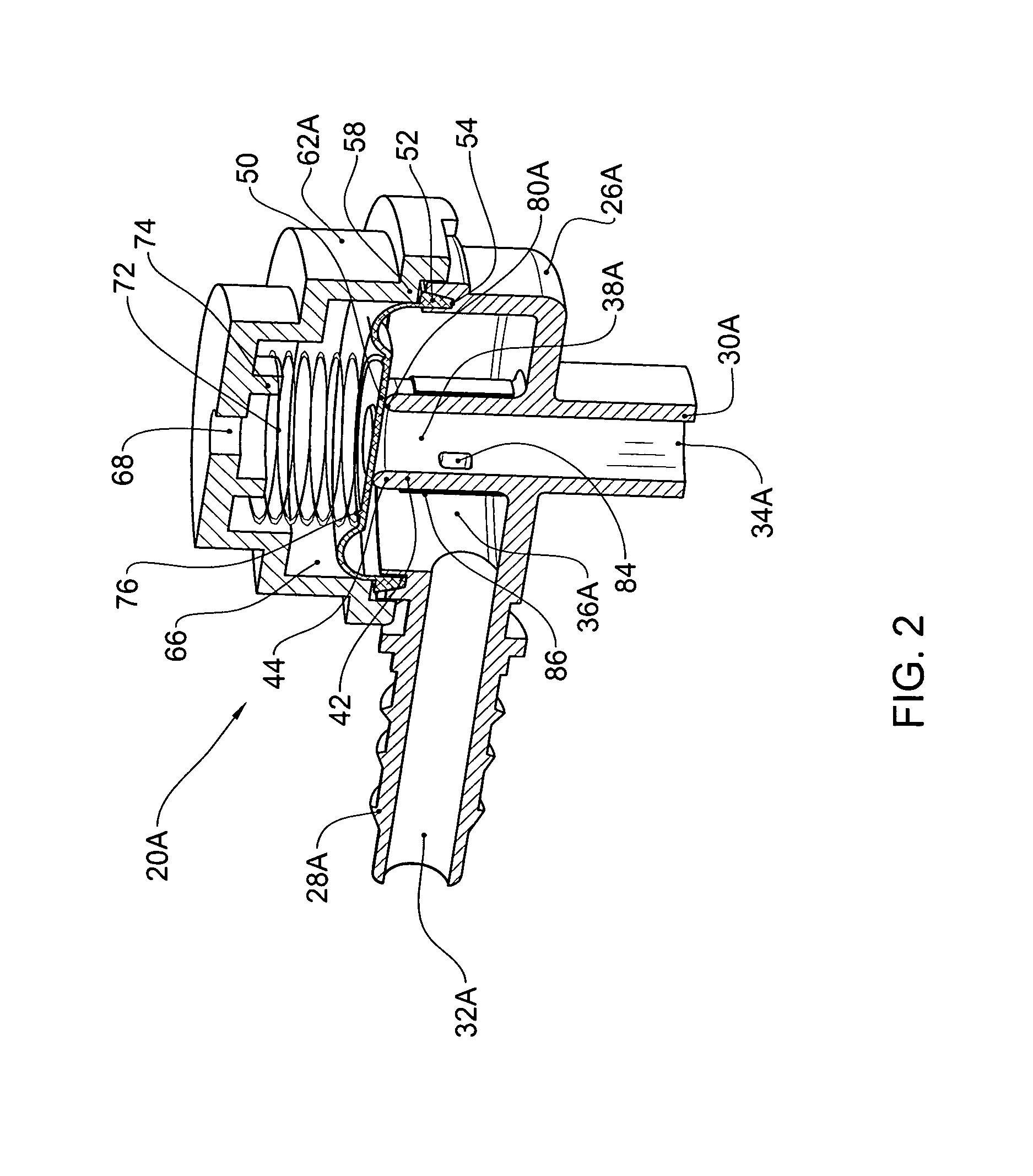
[0045]the invention is disclosed with reference to FIGS. 2 and 3A to 3C illustrating a valve designated 20A comprising a housing 26A fitted with an inlet tube section 28A and an outlet tube section 30A defining an inlet port 32A and an outlet port 34A respectively. Extending within the housing 26A there is an inlet chamber 36A and an outlet chamber 38A partitioned by a tubular wall section 42 formed at its upper end with an annular valve seating 44.

[0046]A peripheral sealing wedge 52 of the diaphragm 50 is sealingly clamped between a peripheral annular groove 54 of housing 26A and a corresponding clamping portion 58 of cover 62A to thus retain the diaphragm 50 and provide sealing engagement such that a control chamber 66 extending above diaphragm 50 is not in flow communication with either the inlet chamber 36A or the outlet chamber 38A.

[0047]In accordance with a modification of the invention, the cover 62A comprises an aperture 68, illustrated in dashed lines, to air the control ch...

second embodiment

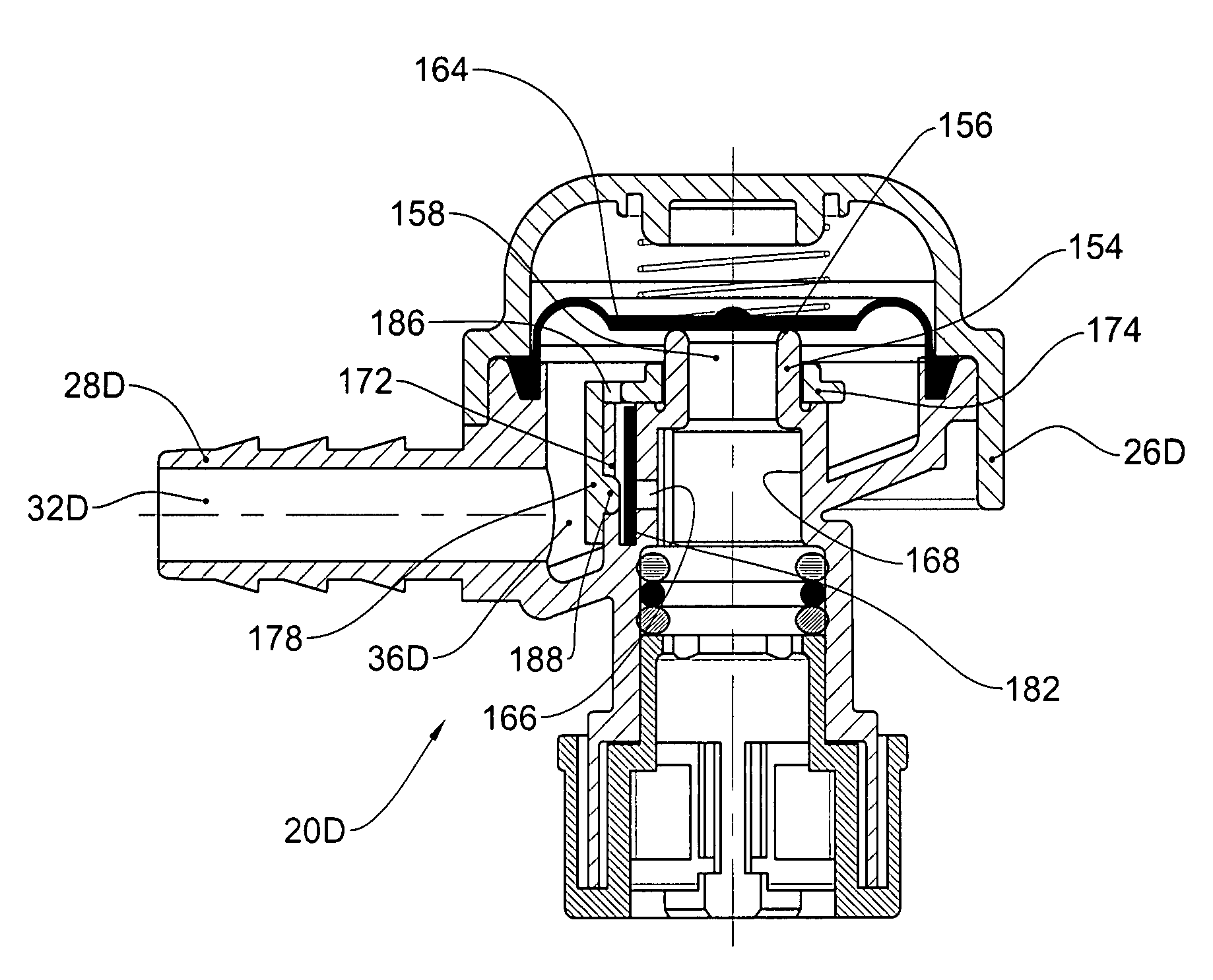
[0065]In FIG. 8 there is illustrated a modification of the second embodiment referred to hereinabove resilient sealing leaf-like member 182. The valve generally designated 20D comprises a housing portion 26D which is basically similar to housing 26A disclosed in connection with FIG. 2 and comprises an inlet tube 28D defining an inlet port 32D connectable to the fuel tank by suitable tubing (not shown) and extending into an annular inlet chamber 36D. A tubular wall portion 154 is formed with a ridge 156 over which extends the first valve controlled passage 158, below the diaphragm 164. A second valve controlled passage in the form of an aperture 166 is formed in wall 168 below the tubular wall portion 154, similar to the arrangement disclosed in connection with the embodiment of FIGS. 2 and 3 with the provision of a shielding member 172 comprising a ring portion 174 for secure mounting over the tubular wall portion 154, and a shielding wall portion 178 extending opposite the aperture...


PUM


Abstract

A fuel vapor control valve comprising a housing fitted with an inlet port connectable to a fuel tank and an outlet port connectable to a fuel vapor recovery device. The inlet port and the outlet port are in flow communication via a first valve controlled passage admitting fuel vapor flow in a direction from the inlet port to the outlet port only when pressure within the fuel tank exceeds a threshold. A second valve controlled passage admits vapor flow in an opposite direction from the outlet port to the inlet port only when pressure within the fuel tank drops below pressure at the fuel vapor recovery device.

Description

FIELD OF THE INVENTION[0001]This invention relates to fluid flow control valves and in particular it is concerned with fuel vapor recovery control valves for mounting in a vehicle between a fuel tank and a fuel vapor recovery device, e.g. a canister, for controlling vapor flow there between.BACKGROUND OF THE INVENTION[0002]A fuel tank of the type typically mounted in a vehicle, is subject to varying pressure owing to several changing parameters, e.g. fuel consumption during operation of the engine (resulting in pressure decrease within the fuel tank), temperature fluctuations (temperature increase results in pressure increase within the fuel tank whilst temperature decrease results in pressure drop within the fuel tank), refueling (resulting in pressure increase within the tank), etc.[0003]Such pressure changes within the fuel tank may have an overall effect on the engine's performance owing to unsteady fuel supply to the engine and, in some extreme cases, may result in deformation ...

Claims


Application Information

Patent Timeline
Patent Type & Authority Patents(United States)
IPC IPC(8): F16K17/24
CPCB60K15/03519B60K2015/03585Y10T137/86324Y10T137/7778B60K15/035
Inventor EHRMAN, MOSHEAKIAN, ILANVULKAN, OMER
Owner RAVAL - AGRI COOP SOCIETIES
Why Eureka
Try Eureka