Connecting system with direct plug connection

a technology of direct plug connection and connection system, which is applied in the direction of coupling device connection, contact member penetrating/cutting insulation/cable strand, electrical apparatus, etc., can solve the problems of limited contact area of conductors and inability to contact conductors having a greater diameter

Active Publication Date: 2009-08-04
WEIDMULLER INTERFACE GMBH & CO KG
View PDF17 Cites 19 Cited by
  • Summary
  • Abstract
  • Description
  • Claims
  • Application Information

AI Technical Summary

Benefits of technology

[0008]According to a primary object of the present invention, a plug-in connector is provided wherein the resilient contact having a clamping portion includes at least two distinct clamping surfaces for selectively engaging the outer circumferential surface of the conductor in accordance with the diametric size thereof. This makes it possible to use the clamping surfaces selectively in order to contact both conductors that have a smaller diameter as well as conductors having a larger diameter, since each of the two clamping pressure areas is activated only in connection with conductors having different diameters.

Problems solved by technology

As a rule, the area of the conductors to be contacted is limited, especially when the clamping leg can be swung around only by a small angle due to the geometric conditions.
This entails the disadvantage that, for example, conducting pins having a greater diameter are not contactable.

Method used


Image

  • Connecting system with direct plug connection
  • Connecting system with direct plug connection
  • Connecting system with direct plug connection

Examples


Embodiment Construction

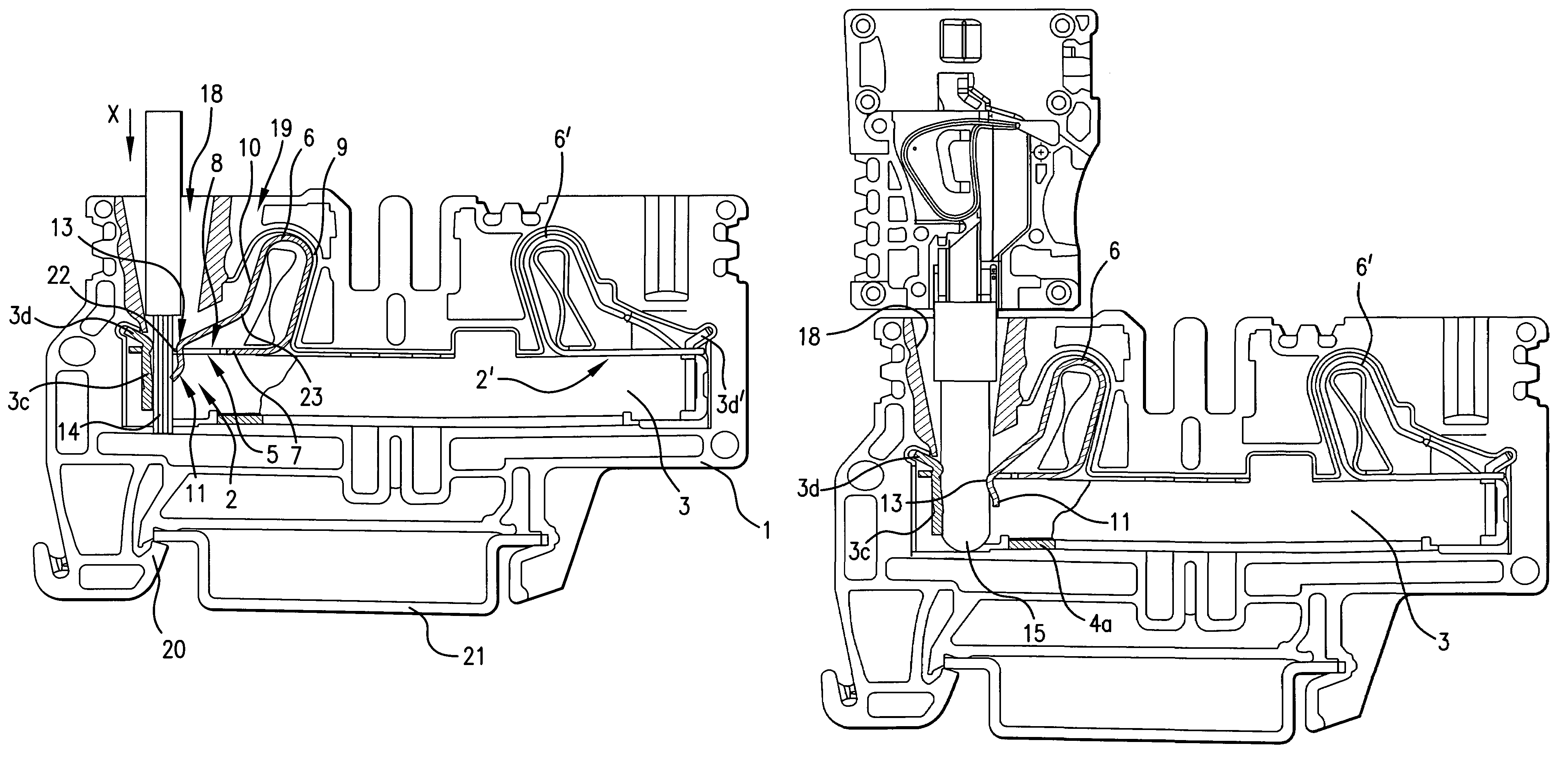
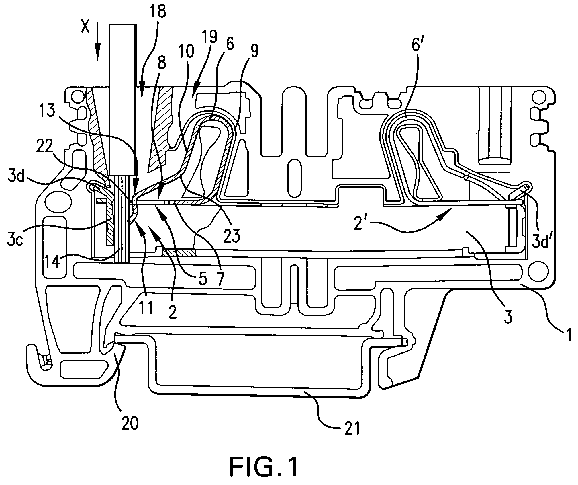
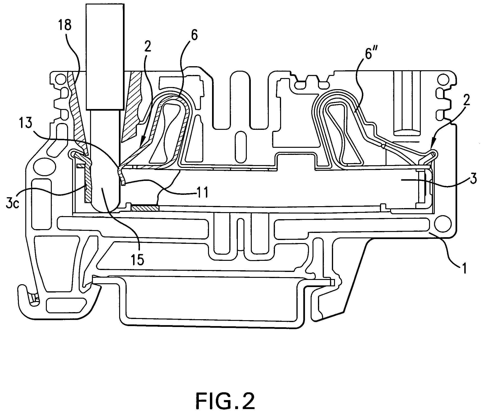
[0015]Referring first more particularly to FIGS. 1 and 4, the connector arrangement of the present invention includes a terminal block 1 formed from an electrically insulating synthetic plastic material containing cavities that receive a pair of connector devices 2, 2′ for electrically connecting the bare ends of a pair of insulated conductors with a horizontal bus bar 3 mounted in a corresponding chamber defined within the terminal block. The bus bar has a generally U-shaped configuration and includes a horizontal bottom wall 3a, a pair of parallel spaced vertical side walls 3b, and a pair of vertical transverse end walls 3c each of which is integrally connected with and bent orthogonally from one of the side and bottom walls, respectively. Two resilient contacts 6, 6′ are mounted in cavities provided in the terminal block, each resilient contact including a fixed horizontal leg portion 7 that is seated transversely upon the upper edges of the bus bar side walls 3b. Normally, the r...


PUM


Abstract

A plug-in connector arrangement includes a terminal block containing a chamber in which are mounted a horizontal bus bar having a transverse wall, and a resilient contact having a fixed horizontal leg portion, an intermediate portion bent upwardly from the first leg portion, and an outwardly biased second leg portion reversely bent back above the first leg portion. The second leg portion contains a clamping end portion that extends through a conductor opening contained in the first leg portion. The clamping portion includes at least two discrete clamping surfaces so arranged that when a bare conductor is inserted into the conductor opening, the conductor circumferential surface is selectively engaged by one or more of the clamping surfaces in accordance with the diametrical size of the conductor. The conductor is biased by the clamping portion toward electrical engagement with the bus bar transverse wall.

Description

BACKGROUND OF THE INVENTION[0001]1. Field of the Invention[0002]A plug-in connector arrangement includes a terminal block containing a chamber in which are mounted a horizontal bus bar having a transverse wall, and a resilient contact having a fixed horizontal leg portion, an intermediate portion bent upwardly from the first leg portion, and an outwardly biased second leg portion reversely bent back above the first leg portion. The second leg portion contains a clamping end portion that extends through a conductor opening contained in the first leg portion. The clamping portion includes at least two discrete clamping surfaces so arranged that when a bare conductor is inserted into the conductor opening, the conductor circumferential surface is selectively engaged by one or more of the clamping surfaces in accordance with the diametrical size of the conductor. The conductor is biased by the clamping portion toward electrical engagement with the bus bar transverse wall.[0003]2. Descri...

Claims


Application Information

Patent Timeline
Patent Type & Authority Patents(United States)
IPC IPC(8): H01R4/24
CPCH01R4/4818H01R4/48185H01R25/14H01R4/48
Inventor DIEKMANN, TORSTEN
Owner WEIDMULLER INTERFACE GMBH & CO KG
Why Eureka
Try Eureka