

Computed tomography system
- Summary
- Abstract
- Description
- Claims
- Application Information
AI Technical Summary
Benefits of technology
Problems solved by technology
Method used
Image

Examples
first embodiment
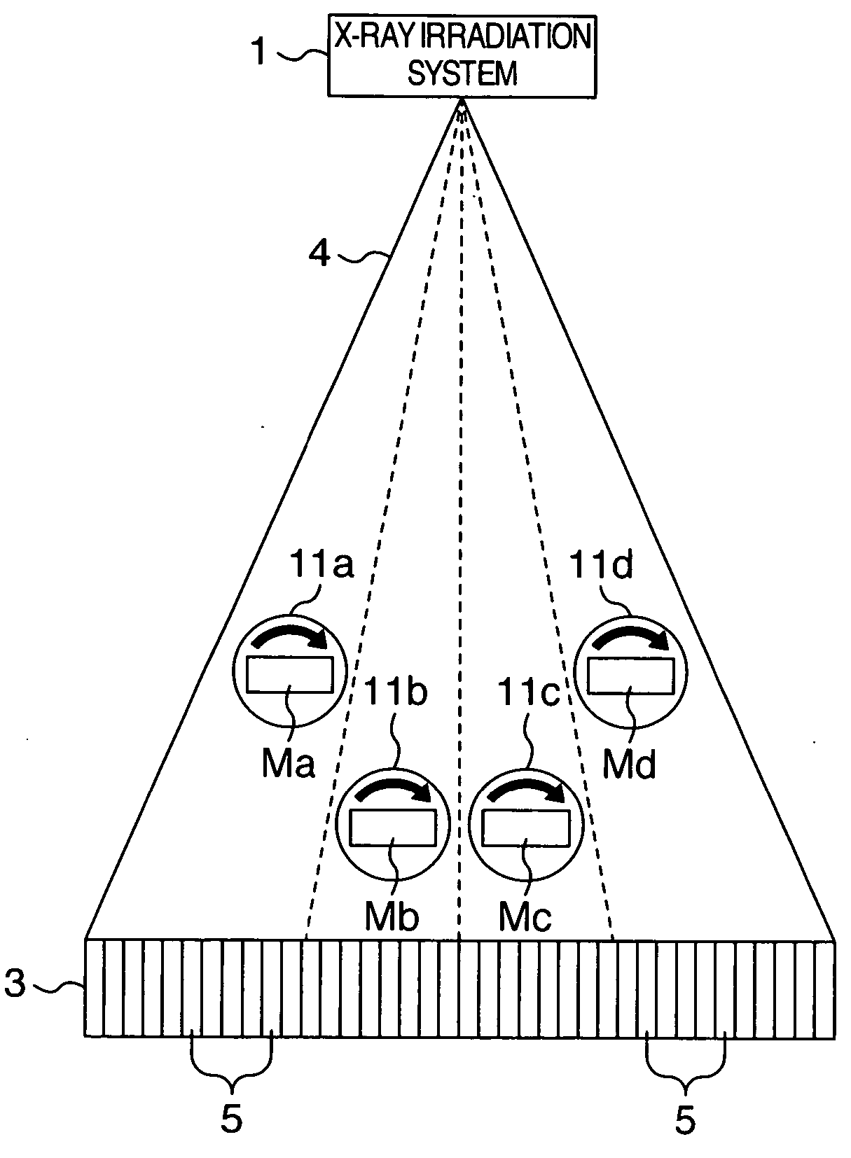
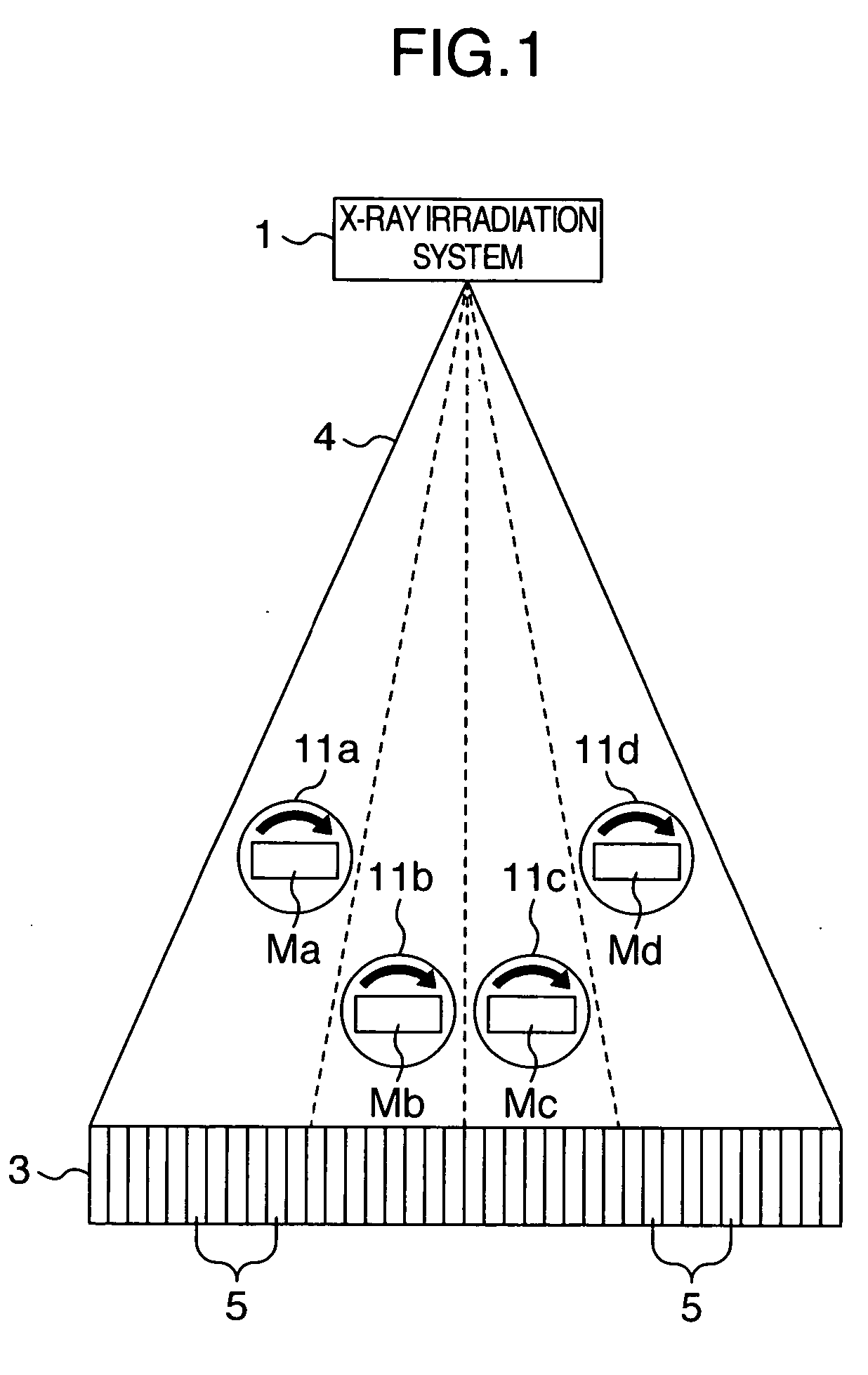
[0022] Embodiments of the present invention will be described. FIG. 1 schematically shows the configuration of a computed tomography system in accordance with a The computed tomography system in accordance with the present embodiment is an X-ray computed tomography system and has the same arrangements as those of the conventional X-ray computed tomography system described for FIG. 4. Arrangements characteristic of the present embodiment will mainly be described below. For the same arrangements as those of the conventional X-ray computed tomography system, read the above description; the description of these arrangements will be appropriately omitted below. The X-ray computed tomography system in accordance with the present embodiment comprises a plurality of, specifically, four turn tables 11a to 11d. The turn tables 11a to 11d are fixedly arranged within the region of irradiation with fan beams 4. Further, the turn tables 11a to 11d are arranged in a relationship such that during ...
second embodiment
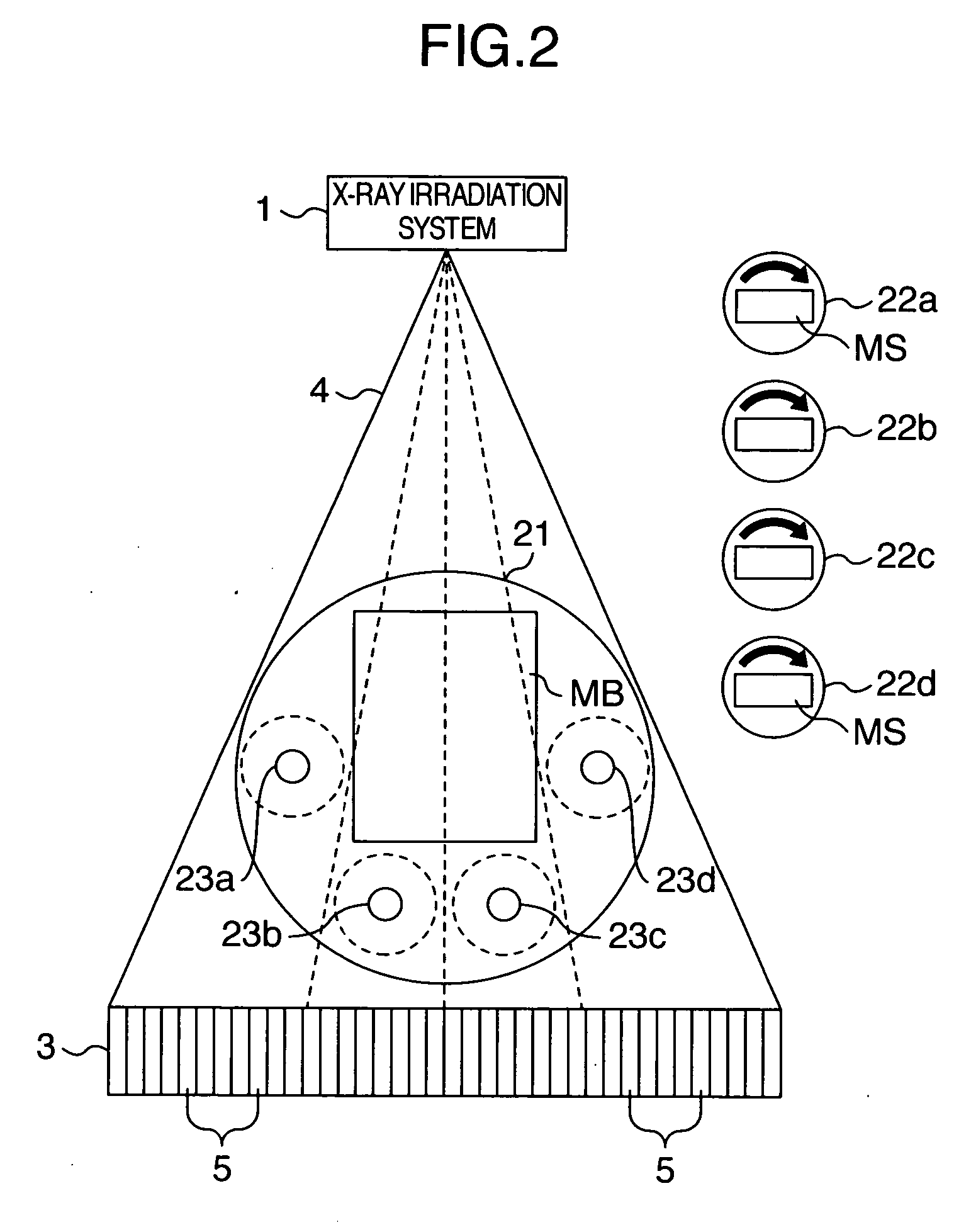
[0026]FIG. 2 schematically shows the configuration of an X-ray computed tomography system that is a computed tomography system in accordance with a The X-ray computed tomography system in accordance with the present embodiment comprises one large turn table 21 and a plurality of, specifically, four small turn tables 22a to 22d. The large turn table 21 and the small turn tables 22 can be selectively used. Specifically, attachment portions 23 (23a to 23d) are provided on the large turn table 21. The small turn tables 22 can be installed on the large turn table 21 as required via the attachment portions 23 so as to be covered by the region of irradiation with the fan beams 4.
[0027] Such an X-ray computed tomography system picks up images as described below. If testing objects that are image pickup targets are large, only one testing object MB is placed on the large turn table 21 for image pickup. On the other hand, if testing objects that are image pickup targets are small, the attach...
PUM
 Abstract
Description
Claims
Application Information