

Rotation transmitting apparatus and vehicle steering apparatus
a transmission device and steering device technology, applied in the direction of non-deflectable wheel steering, gearing, vehicle components, etc., can solve the problems of increasing the number of components and assembling processes, abnormal sound generation, and abnormal sound generation at the mesh portion, so as to reduce the number of components, reduce the collision sound of the gears, and reduce the effect of sliding sound
- Summary
- Abstract
- Description
- Claims
- Application Information
AI Technical Summary
Benefits of technology
Problems solved by technology
Method used
Image

Examples
embodiment 1
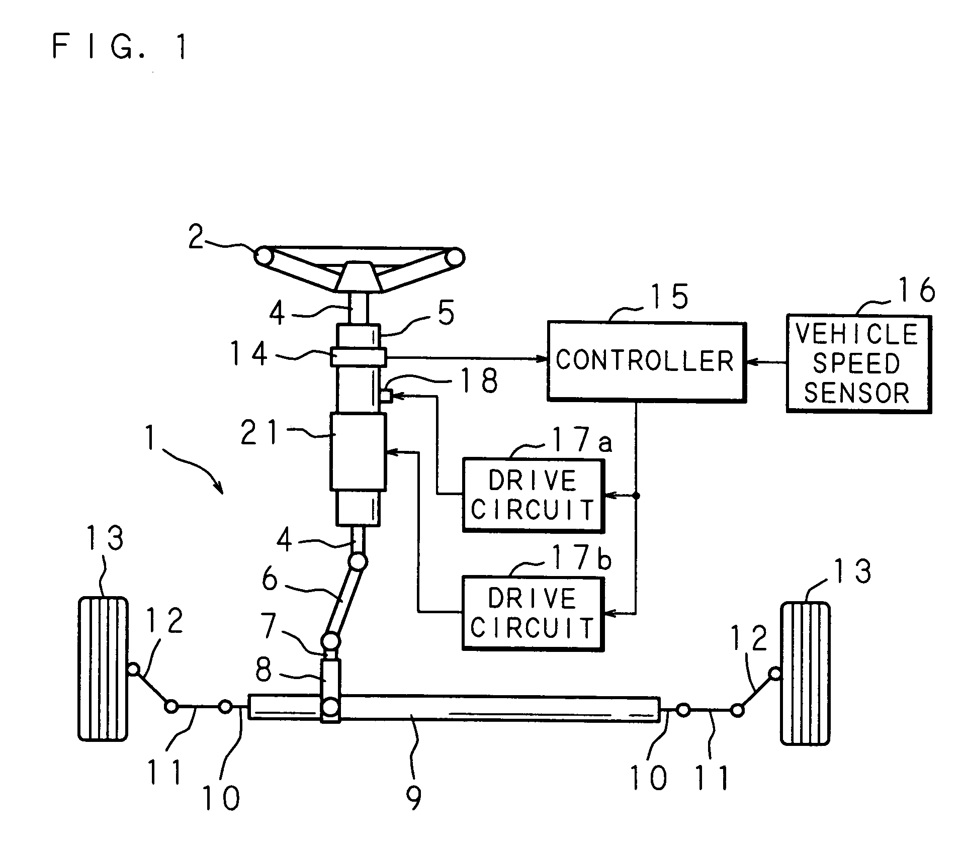
[0038]FIG. 1 is a schematic view showing an example of application of a rotation transmitting apparatus according to the present invention in a steering apparatus for a vehicle. In FIG. 1, a reference numeral 1 denotes a rack and pinion type steering apparatus which includes a rack shaft 10 supported in a freely movable manner in an axial direction on an interior of a cylindrical rack housing 9 extending in a left-and-right direction of a vehicle body. Tie rods 11 are coupled to both ends of the rack shaft 10 that protrude from both sides of the rack housing 9. Ends of the tie rods 11 on the opposite side of the coupling portions with the rack shaft 10, are connected with wheels 13 for steering via respective knuckle arms 12. When the rack shaft 10 moves in the axial direction, the knuckle arms 12 are pushed / pulled via the tie rods 11 so as to steer the wheels 13 to the left or right.
[0039]A pinion housing 8 in a cylindrical shape which intersects with the rack housing 9 is continuo...
embodiment 2
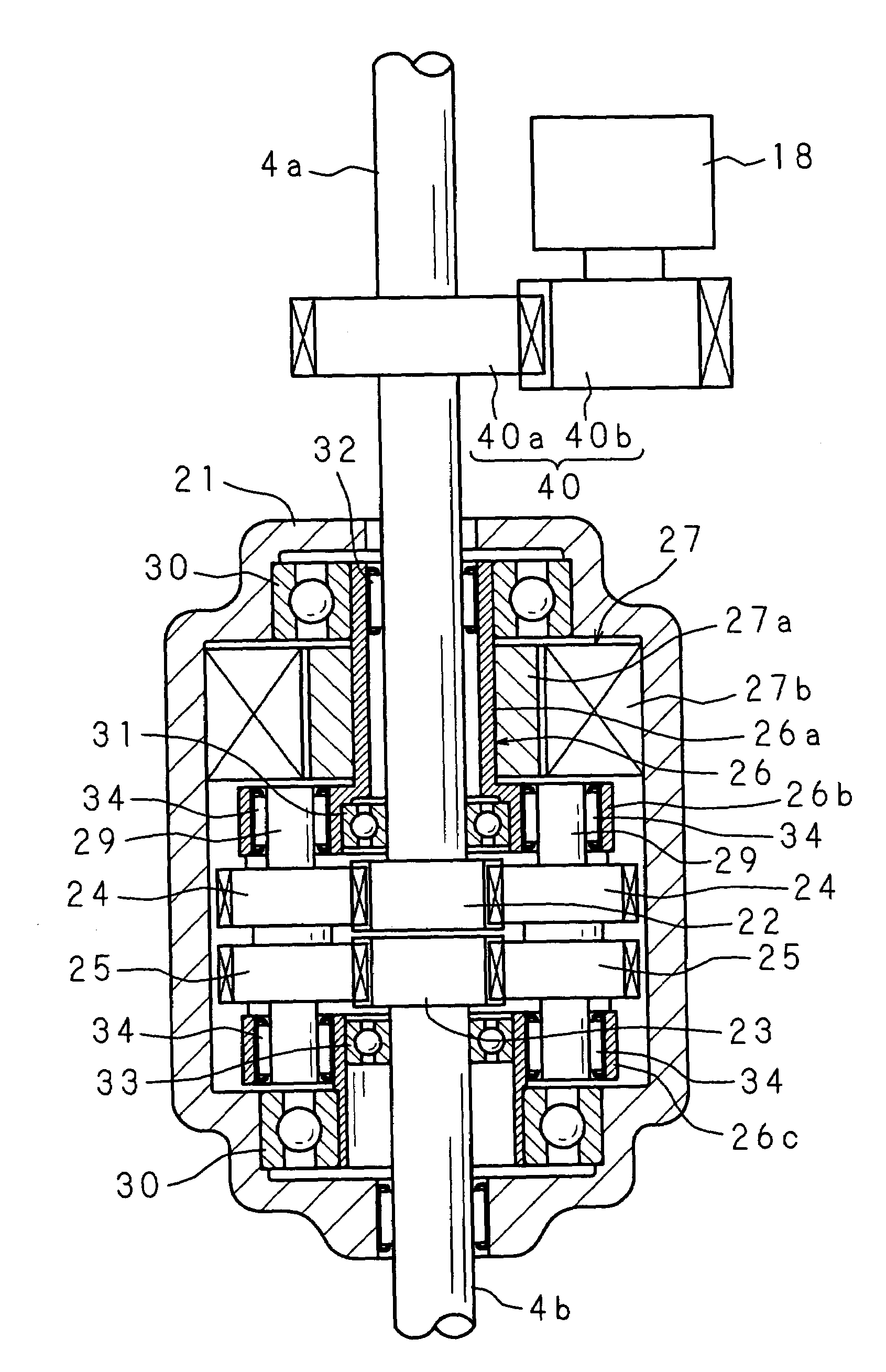
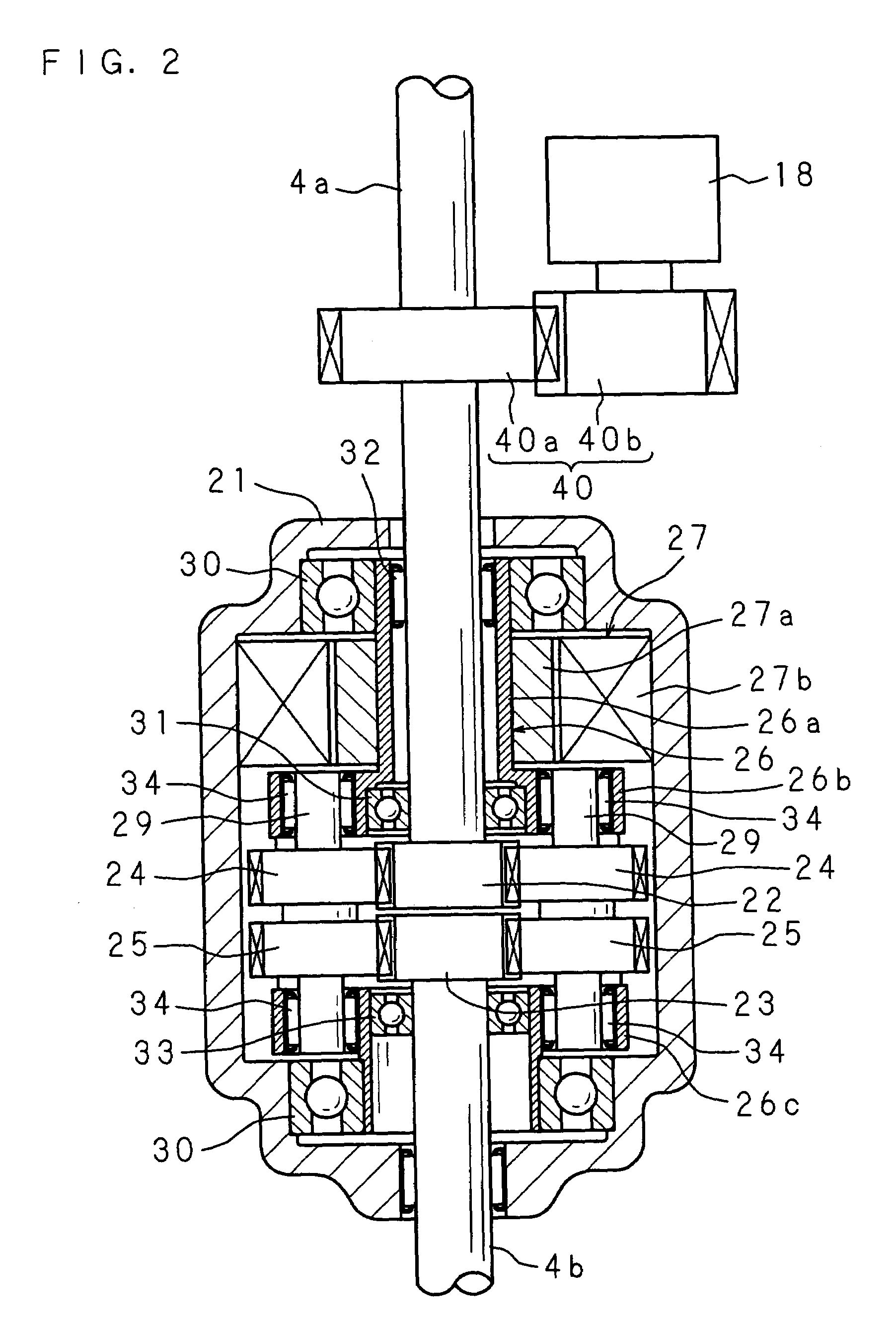
[0058]FIG. 4 is a sectional view showing a construction of Embodiment 2 of the vehicle steering apparatus according to the present invention. FIG. 5 is an enlarged sectional view of a main part. FIG. 6 is a schematic perspective view of a carrier portion.
[0059]This vehicle steering apparatus includes an input shaft 51, an output shaft 52, a first electric motor 53, a second electric motor 54 and a controller 55. Herein, the input shaft 51 has one end connected to a steering wheel serving as steering means. The output shaft 52 has one end interlockingly coupled to the other end of the input shaft 51 by a differential mechanism A and the other end connected to, for example, a rack and pinion type steering mechanism. The first electric motor 53 serves as a first actuator for rotating the output shaft 52 with respect to the input shaft 51 while increasing a rotational speed. The second electric motor 54 is used for a reaction force for applying a required torque to the input shaft 51 in...
embodiment 3
[0080]FIG. 7 is a schematic view showing a construction of Embodiment 3 of the vehicle steering apparatus according to the present invention. This vehicle steering apparatus includes a differential mechanism D, a first electric motor 84 and a second electric motor 85. Herein, the differential mechanism D has an input shaft 51 and output shaft 52 which are coaxially arranged so as to be freely rotatable, a sun gear 80 which is fitted to and supported on the output shaft 52 so as to be freely rotatable, an internal gear 81 which is arranged around an outer periphery of the sun gear 80 so as to be freely rotatable and is interlockingly coupled with the input shaft 51 coaxially, plural planetary gears 82 which are meshed with the sun gear 80 and the internal gear 81, and a carrier 83 which supports the planetary gears 82 and is interlockingly coupled with the output shaft 52 coaxially. The first electric motor 84 is arranged around an outer periphery of the output shaft 52 and allows th...
PUM
 Abstract
Description
Claims
Application Information