Method and apparatus for preventing multiple attempted firings of a semiconductor switch in a load control device

a load control device and semiconductor technology, applied in the direction of power conversion systems, instruments, light sources, etc., can solve the problems of increasing the temperature of the transformer, affecting the operation of the transformer, and affecting the operation of the mlv transformer,

Active Publication Date: 2009-08-04
LUTRON TECH CO LLC
View PDF10 Cites 58 Cited by
  • Summary
  • Abstract
  • Description
  • Claims
  • Application Information

AI Technical Summary

Benefits of technology

[0017]According to the present invention, a two-wire load control device for controlling the amount of power delivered to a load from a source of AC power comprises a semiconductor switch, a timing circuit, a trigger circuit, and a clamp circuit. The semiconductor switch is operable to be coupled in series electrical connection between the source and the load. The semiconductor switch has a control input for controlling the semiconductor switch between a non-conductive state and a conductive state. The timing circuit is coupled in parallel electrical connection with the semiconductor switch and has an output for providing a timing voltage signal. The trigger circuit is coupled to the output of the timing circuit and is operable to control the semiconductor switch. A trigger voltage, which increases in magnitude with respect to time in response to the timing voltage signal, develops across the trigger circuit. The trigger circuit is characterized by a variable voltage threshold having an initial magnitude. The semiconductor switch is operable to change between the non-conductive and conductive states in response to a conduction of a control current through the trigger circuit. The clamp circuit is coupled to the output of the timing circuit for limiting the magnitude of the timing voltage to a clamp magnitude greater than the initial magnitude. When the timing voltage exceeds the initial magnitude of the variable voltage threshold after the beginning of a half-cycle of the AC power source, the trigger circuit is operable to (1) conduct the control current, (2) reduce the timing voltage to a predetermined magnitude less than the initial magnitude, and (3) increase the variable voltage threshold to a second magnitude greater than the clamp magnitude. Accordingly, the timing voltage is prevented from exceeding the second magnitude.
[0019]The present invention further provides a method of controlling a semiconductor switch in a load control device for controlling the amount of power delivered to a load from an AC power source. The method comprises the steps of: (1) generating a trigger voltage which increases in magnitude with respect to time during a half-cycle of the AC power source; (2) determining when the trigger voltage exceeds a variable voltage threshold having an initial voltage threshold; (3) conducting a gate current through a control input of the semiconductor device when the trigger voltage exceeds the initial voltage threshold; (4) increasing the variable voltage threshold from the initial voltage threshold to a second voltage threshold greater than the initial voltage threshold; and (5) preventing the trigger voltage from exceeding the second threshold voltage within the half-cycle of the AC power source.

Problems solved by technology

One problem with low-voltage lighting loads employing a transformer, specifically MLV loads, is that the transformers are susceptible to any direct-current (DC) components of the voltage provided across the transformer.
A DC component in the voltage across the transformer can cause the transformer to generate acoustic noise and to saturate, increasing the temperature of the transformer and potentially damaging the transformer.
Thus, an asymmetric load current iL will flow through the MLV load 16, causing the MLV transformer 16A to generate acoustic noise and to overheat, which can potentially damage the MLV transformer.

Method used


Image

  • Method and apparatus for preventing multiple attempted firings of a semiconductor switch in a load control device
  • Method and apparatus for preventing multiple attempted firings of a semiconductor switch in a load control device
  • Method and apparatus for preventing multiple attempted firings of a semiconductor switch in a load control device

Examples


first embodiment

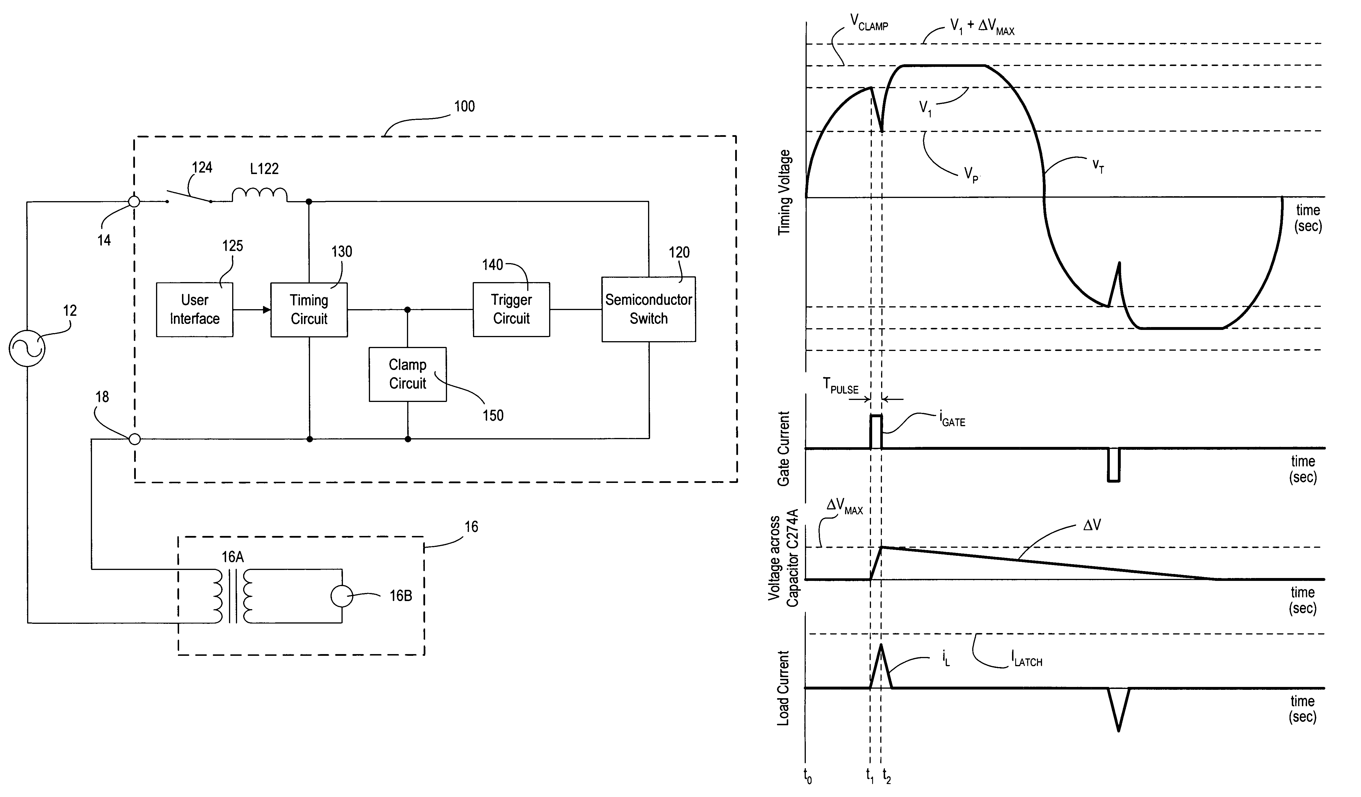
[0040]FIG. 6 is a simplified schematic diagram of an MLV dimmer 200 according to the present invention. The MLV dimmer 200 comprises a triac 220 having a pair of main terminals coupled in series electrical connection between the AC power source 12 and the MLV load 16. The triac 220 has a control input, i.e., a gate terminal, for rendering the triac 220 conductive. The MLV dimmer 200 further comprises a timing circuit 230 coupled in parallel with the main terminals of the triac 220 and comprising a potentiometer R232 in series with a capacitor C234. A timing voltage signal vT is generated at an output, i.e., the junction of the potentiometer R232 and the capacitor C234, and is provided to a trigger circuit 240. The resistance of the potentiometer R232 may be varied in response to the actuation of a slider control of a user interface of the dimmer 200 (for example, the slider control 128 of the user interface 125).

[0041]The trigger circuit 240 is coupled in series electrical connectio...

second embodiment

[0047]FIG. 8 is a simplified schematic diagram of an MLV dimmer 300 according to the present invention. The MLV dimmer 300 includes a triac 320 in series electrical connection between the HOT terminal 14 and DIMMED HOT terminal 18 and a timing circuit 330 coupled in parallel with the triac. The timing circuit 330 comprises a potentiometer R332, a capacitor C334, and a calibrating resistor R336. The timing circuit operates in a similar manner to the timing circuit 230 of the MLV dimmer 200 to produce a timing voltage signal vT at an output.

[0048]The MLV dimmer further includes a rectifier bridge comprising four diodes D342A, D342B, D342C, D342D; a trigger circuit comprising a break-over circuit 360 and an offset circuit 370; a current limit circuit 380; and an optocoupler 390. The break-over circuit 360, the current limit circuit 380, and a photodiode 390A of the optocoupler 390 are connected in series across the DC-side of the rectifier bridge. The offset circuit 370 is connected su...

third embodiment

[0056]FIG. 10 is a simplified schematic diagram of an MLV dimmer 400 according to the present invention. The dimmer 400 includes the same or very similar circuits as the MLV dimmer 300. However, the circuits of FIG. 10 are coupled together in a different manner.

[0057]The MLV dimmer 400 includes a clamp circuit 450, which is coupled across the photodiode 390A of the optocoupler 390, the break-over circuit 360, and an offset circuit 470 rather than across the AC-side of the rectifier bridge as in the MLV dimmer 200. During the positive half-cycles, a capacitor C474A in the offset circuit 470 charges to a voltage ΔV, thus increasing the voltage threshold VTH to the voltage ΔV plus an initial voltage threshold V1. Once again, the voltage ΔV across the capacitor C474A is substantially zero volts at the beginning of the positive half-cycles, and thus, the initial voltage threshold V1 is equal to the break-over voltage VBR, e.g., approximately 30V, of the break-over circuit 360 plus the ad...


PUM


Abstract

A two-wire load control device, such as a dimmer, is operable to control the amount of power delivered to an electrical load, such as a magnetic low-voltage (MLV) load, and comprises a bidirectional semiconductor switch, a timing circuit, a trigger circuit having a variable voltage threshold, and a clamp circuit. When a timing voltage signal of the timing circuit exceeds an initial magnitude of the variable voltage threshold, the trigger circuit is operable to render the semiconductor switch conductive, reduce the timing voltage signal to a predetermined magnitude less than the initial magnitude, and to increase the variable voltage threshold to a second magnitude greater than the first magnitude. The clamp circuit limits the magnitude of the timing voltage signal to a clamp magnitude between the initial magnitude and the second magnitude, thereby preventing the timing voltage signal from exceeding the second magnitude. Accordingly, multiple attempted firings of the semiconductor switch are avoided, and the MLV dimmer is prevented from conducting asymmetric current when an MLV transformer of the MLV load is unloaded.

Description

RELATED APPLICATIONS[0001]This application claims priority to commonly-assigned U.S. Provisional Application Ser. No. 60 / 783,538, filed Mar. 17, 2006, entitled DIMMER FOR PREVENTING ASYMMETRIC CURRENT FLOW THROUGH AN UNLOADED MAGNETIC LOW VOLTAGE TRANSFORMER, the entire disclosure of which is hereby incorporated by reference.BACKGROUND OF THE INVENTION[0002]1. Field of the Invention[0003]The present invention relates to load control devices for controlling the amount of power delivered to an electrical load. More specifically, the present invention relates to drive circuits for a two-wire analog dimmer that prevent asymmetric current flow through a magnetic low-voltage (MLV) load.[0004]2. Description of the Related Art[0005]A typical lighting dimmer is coupled between a source of alternating-current (AC) power (typically 50 or 60 Hz line voltage AC mains) and a lighting load. Standard dimmers use one or more semiconductor switches, such as triacs or field effect transistors (FETs), ...

Claims


Application Information

Patent Timeline
Patent Type & Authority Patents(United States)
IPC IPC(8): G05F1/613
CPCH05B39/08
Inventor SALVESTRINI, CHRISTOPHER JAMES
Owner LUTRON TECH CO LLC
Why Eureka
Try Eureka