Auxiliary mesh type starter

a mesh type, starter technology, applied in the field of starters, can solve the problems of electromagnetic switch burnout, electromagnetic switch prone to failure, electromagnetic switch burnout, etc., to prevent the breakage of electromagnetic switch, isolator or the like, and smooth disconn

Active Publication Date: 2015-04-09
PRESTOLITE ELECTRIC BEIJING
View PDF5 Cites 13 Cited by
  • Summary
  • Abstract
  • Description
  • Claims
  • Application Information

AI Technical Summary

Benefits of technology

[0019]In said auxiliary mesh type starter, the attracting coil is a means for limiting the magnitude of current.
[0024](1) The head end of the attracting coil and the head end of the holding coil in the electromagnetic switch are connected separately and are controlled separately by different relays. In this way, the number of turns of the attracting coil needs not be the same as that of the holding coil, the number of turns of the holding coil may differ greatly from the number of turns of the attracting coil, and the attracting coil can be freely adjusted according to the required torque for meshing. Thus, the starter can generate a sufficiently large slow-turning torque, avoid the fault that the driving gear cannot rotate to mesh with the flywheel gear ring when the driving gear contacts the end face of the flywheel gear ring, avoid the faults of pushing against the gear, effectively decrease the possibility of burning out the electromagnetic switch, and prolong the service life of the starter.
[0026](3) When power is off, the attracting coil and the holding coil of the electromagnetic switch would not form a series circuit, the two coils are in the off state, and thus the main contact point of the electromagnetic switch can be smoothly disconnected.
[0027](4) When the relay that controls the attracting coil is a time relay, after the attracting coil is powered on for a short time (e.g., within 2 s), it is forced to be powered off, that is, the attracting coil stops working, so that in abnormal conditions (e.g., when the flywheel gear ring and the driving gear do not match properly and the latter cannot mesh with the former), the attracting coil would not have a large current flowing through it for a long time, thereby avoiding the fault of burning out the electromagnetic switch that is caused for particular and abnormal conditions. Similarly, a time relay (e.g., which is automatically disconnected after 30 s) can also be chosen as the relay that controls the holding coil, thereby avoiding the longtime power on of the holding coil that is caused for particular and abnormal conditions, and thereby preventing the armature, electromagnetic switch, isolator or the like from breaking down.
[0028](5) The attracting coil may be made of a material having a higher resistivity, such as an aluminum enamelled wire, copper clad aluminum enamelled wire, constantan enamelled wire, iron wire, etc., thereby not only reducing the acting force that the driving gear of the starter applies to the end face of the flywheel gear ring but also reducing the cost of the electromagnetic switch.
[0029](6) After the acting force that the driving gear applies to the end face of the flywheel gear ring is reduced, the extent of damage to the end face of the flywheel gear ring can be significantly reduced, thereby significantly prolonging the service time of the flywheel gear ring and fully satisfying the requirement for a starter with an idle start-stop system. In addition, as a small acting force is transmitted, the service lives of other parts (e.g., the shift fork, the driving gear, the isolator, and the electromagnetic switch, etc.) of the meshing system in the starter can be improved accordingly.

Problems solved by technology

(1) Since the head end of the attracting coil and the head end of the holding coil of the electromagnetic switch in this type of starter are connected together, in order to guarantee the reliable power off of the electromagnetic switch, the attracting coil and the holding coil of the electromagnetic switch must have substantially the same effective number of turns and, in the meanwhile, the holding coil must not have too few turns. This means that the attracting coil must also have quite a few turns. Although the starter can be enabled to rotate slowly before the closure of the main contact point of the electromagnetic switch by a method which comprises appropriately increasing the coil diameter of the attracting coil and reducing the number of turns of the attracting coil, the number of turns of the attracting coil cannot be reduced sharply, otherwise the number of turns of the holding coil has to be reduced drastically with an eye to the reliable power off of the electromagnetic switch. Because of the limited torque for the flexible meshing of this type of starter, in some cases, the driving gear cannot mesh with the flywheel gear ring and accordingly is pushed against the gear. As a consequence, the driving gear cannot mesh with the flywheel gear ring, thus the attracting coil is forced to be energized for a long time while a relatively large current flows through the coil, so the electromagnetic switch is prone to failure.
(2) Because a relatively large current flows through the attracting coil which has quite a few turns, a large electromagnetic force is generated by the electromagnetic switch and accordingly the driving gear applies a too large acting force to the end face of the flywheel gear ring, thereby badly damaging the end face of the flywheel gear ring; furthermore, since the driving gear applies a too large acting force to the end face of the flywheel gear ring, the driving gear of the starter is liable to be pushed against the gear, and if so, the transmission of the driving gear will be impeded by a high drag torque, and the fault that the electromagnetic switch is burnt out will easily occur as the driving gear is pushed against the gear for a long time.
(3) In order to ensure that a sufficiently large current flows through the attracting coil, the attracting coil has not many turns, thus the holding coil has not many turns, too, the coil has a higher current density, and the starter works for a long time, keeping elevating the temperatures of the coils too rapidly. Due to heat conduction, the attracting coil has a too high temperature, the starter has a too small braking torque for flexible meshing when it starts up again, then the faults of pushing against the gear and of burning out the electromagnetic switch would easily occur in the starter. If a method comprising increasing the coil diameter of the holding coil and rewinding it is employed for reducing the current density of the holding coil, such coil assembly is poor in winding process and the cost of the holding coil is high.
(4) In some abnormal conditions, e.g., when the flywheel gear ring and the driving gear do not match properly, the main contact point of the electromagnetic switch cannot be closed, then the attracting coil is compelled to have a large current flowing through it for a long time, so the fault of burning out would occur to the electromagnetic switch easily.

Method used


Image

  • Auxiliary mesh type starter
  • Auxiliary mesh type starter
  • Auxiliary mesh type starter

Examples


example 1

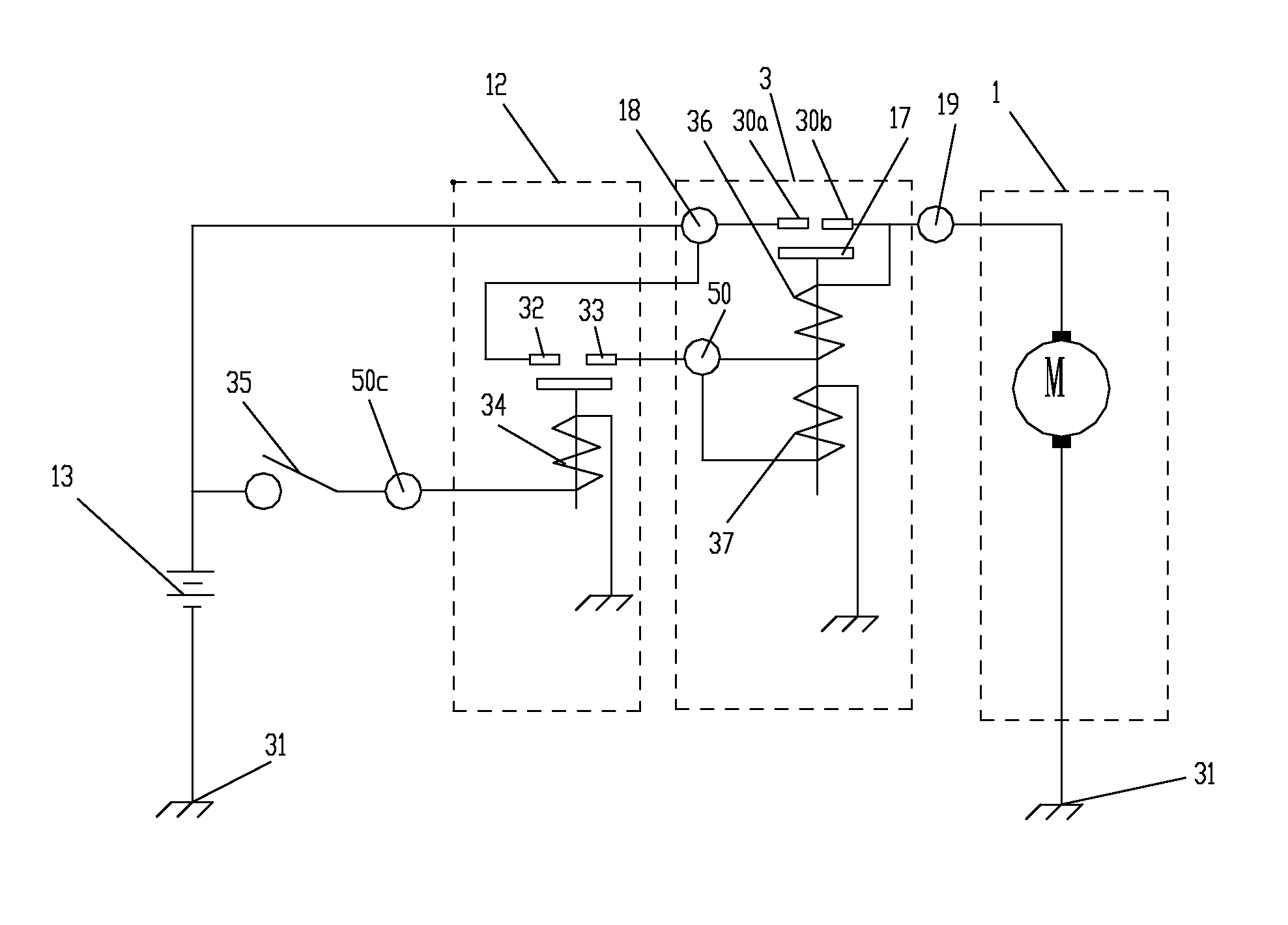
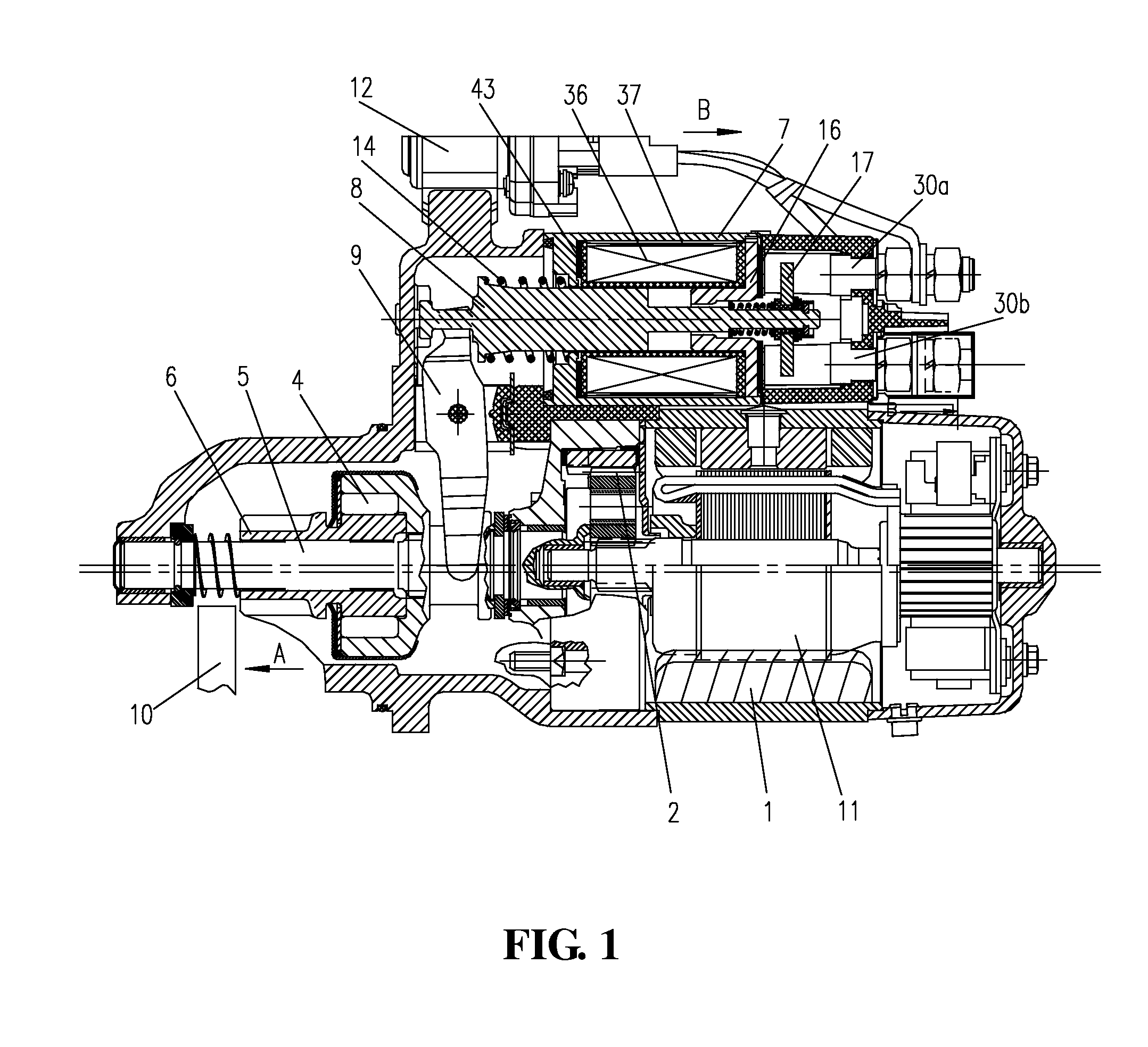
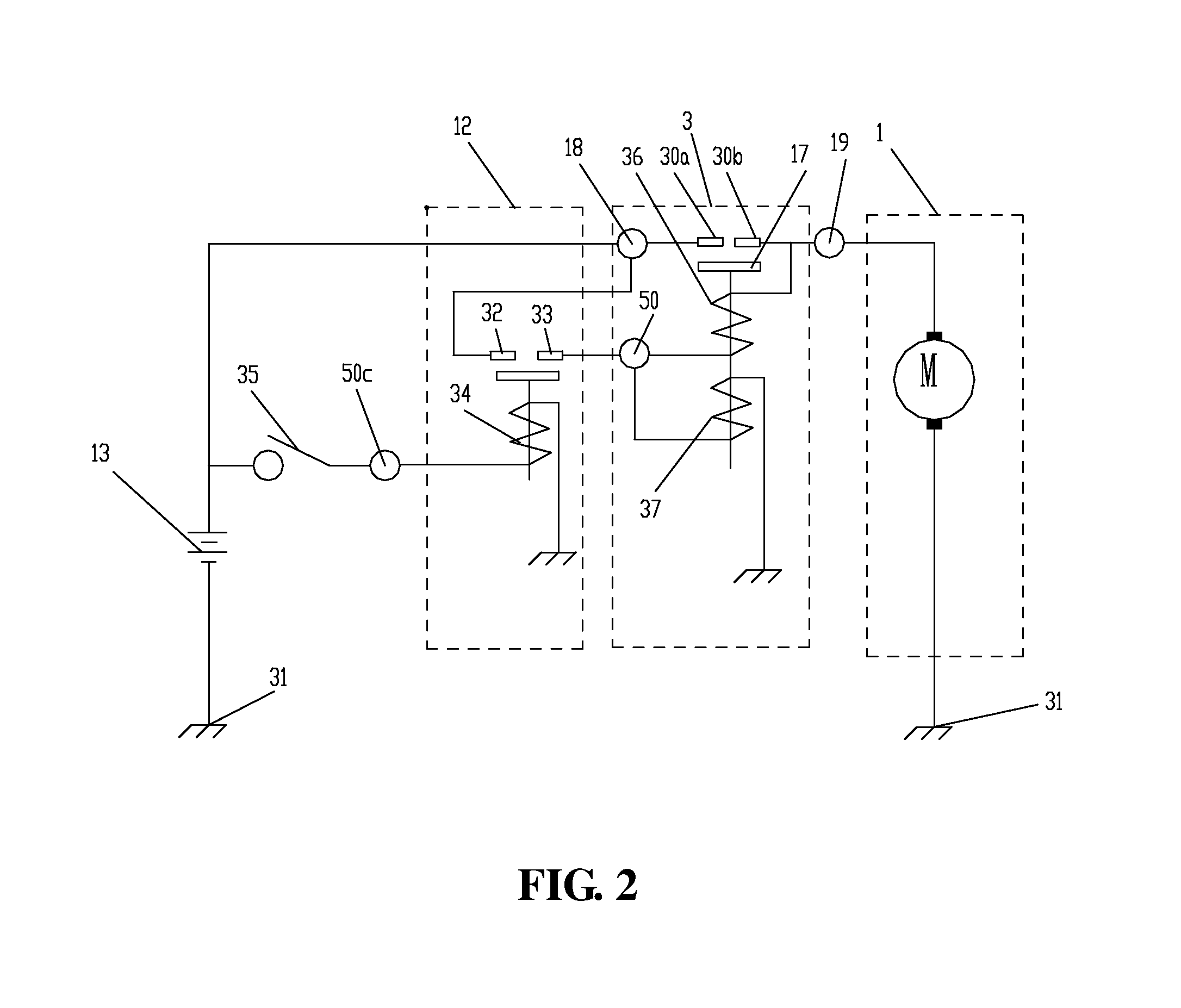
[0071]Referring to FIG. 3, the auxiliary mesh type starter according to the present invention, which is substantially similar in structure to the auxiliary mesh type starter as shown in FIG. 1, also comprises a motor 1, an electromagnetic switch 3 connected to the motor 1 and relays 12 connected to the electromagnetic switch 3, wherein the relays 12 are connected to a key switch 35. The electromagnetic switch 3 is essentially the same as a common auxiliary mesh type electromagnetic switch, i.e., the electromagnetic switch 3 still controls the power on / off of the motor 1 using a pair of contact points, except that the head end of the attracting coil 36 and the head end of the holding coil 37 are connected separately and are controlled separately by two relays. To be specific, the relays 12 include a first relay and a second relay, wherein the first relay includes contact points 321, 331 and a coil 341, with the head end (which is connected to the terminal 50 I) of the attracting coil...

example 2

[0076]Referring to FIG. 4, the structure in this example is substantially the same as the structure in Example 1. The difference is: in this embodiment, the number of turns of the attracting coil is zero; preferably, the attracting coil 36 is a means for limiting the magnitude of current, i.e., the attracting coil 36 can be regarded as a current limiting resistor 36′, and the slow-turning torque of the starter is adjusted by adjusting the current limiting resistor 36′. That is to say, in this example, the electromagnetic switch 3 only has one coil (the holding coil 37), the electromagnetic force generated by the coil plays a role in holding the plunger 8 and also in attracting the plunger 8. Since the other structures are essentially the same as those described in Example 1, details are not repeated herein.

[0077]This example has the following advantages:

[0078](1) Since the slow-turning torque of the starter is adjusted through the current limiting resistor, the magnitude of current ...

example 3

[0081]Referring to FIG. 5, the structure in this example is substantially the same as the structure in Example 1, i.e., two relays are used to control the attracting coil 36 and the holding coil 37, respectively. The difference is: in this embodiment, the first relay that controls the attracting coil 36 is a time relay, i.e., the attracting coil 36 is controlled by a delay relay, so, after the attracting coil 36 is powered on for a short time (e.g., within 2 s), the contact points of the first relay are compelled to be disconnected so that in abnormal conditions (e.g., when the flywheel gear ring 10 and the driving gear 6 do not reasonably match and the latter cannot mesh with the former), the attracting coil 36 would not have a large current flowing through it for a long time, thereby avoiding the fault of burning out the electromagnetic switch that is caused for particular and abnormal conditions.

[0082]Similarly, the second relay that controls the holding coil 37 can also be a tim...


PUM


Abstract

An auxiliary mesh type starter, comprising a motor, an electromagnetic switch connected with the motor and relays connected with the electromagnetic switch, wherein the electromagnetic switch comprises a holding coil, an attracting coil, a stop seat arranged at the rear end parts of the holding coil and the attracting coil, a plunger arranged on the inner circumferences of the holding coil and the attracting coil and capable of sliding in an axial direction, a return spring for applying return force to the plunger, and a contact point arranged at the rear end of the plunger; and the relays are connected to a key switch, wherein the relays comprise a first relay and a second relay, with the head end of the attracting coil connects to the key switch via the first relay, and the head end of the holding coil connects to the key switch via the second relay.

Description

TECHNICAL FIELD[0001]The present invention relates to a starter, and more particularly to an auxiliary mesh type starter.BACKGROUND ART[0002]FIG. 1 is a cross-sectional view of the currently existing auxiliary mesh type starter. As shown in FIG. 1, the auxiliary mesh type starter which applies a starting torque to an engine has the following structure: a speed reducer 2 is adapted to decelerate the rotational torque of an armature 11 in a motor 1 and to increase rotational torques, and an isolator 4 is mounted on a driving gear 6 of an output shaft 5 and is driven by the motor 1 to rotate.[0003]Referring to FIG. 2, an auxiliary mesh type starter comprises a motor 1, an electromagnetic switch 3 and relays 12. In the auxiliary mesh type starter, the electromagnetic switch 3 comprises an attracting coil 36, a holding coil 37 (the holding coil 37 and the attracting coil 36 are arranged on a coil frame 43), an solenoid body 7 circumferentially surrounds the outer sides of the attracting ...

Claims


Application Information

Patent Timeline
Patent Type & Authority Applications(United States)
IPC IPC(8): F02N11/08F02N11/02
CPCF02N11/0851F02N11/02F02N11/087F02N15/067H01H47/22H01H51/065
Inventor QIN, SUNSHINEHU, ROBINLI, BIG
Owner PRESTOLITE ELECTRIC BEIJING
Why Eureka
Try Eureka