Method and device for operating an inductive load with different electric voltages

a technology of electric voltage and inductive load, which is applied in the direction of positive displacement liquid engine, magnetic body, machine/engine, etc., can solve the problems of unacceptably high stress on components, high cost of compensation, and rise to such a magnitude, so as to limit the magnitude of current rise and current rise. the effect of the current ris

Inactive Publication Date: 2005-06-16
ROBERT BOSCH GMBH
View PDF9 Cites 15 Cited by
  • Summary
  • Abstract
  • Description
  • Claims
  • Application Information

AI Technical Summary

Benefits of technology

[0007] The method according to the present invention for operating an inductive load has the advantage that the current rise in the inductive load can be influenced by selecting pulse lengths and pulse pauses of the electric voltage. This procedure advantageously allows for the time characteristic of the current rise to be shaped in diverse ways and to adapt them to the respective requirements. In particular, it is possible to limit the magnitude of the current rise and thus to protect the inductive load from being destroyed by an excessively high current. This advantageously also allows for an operation in higher voltage ranges, which until now were not accessible due to the high current rise to be expected.
[0009] According to a further preferred specific embodiment, a current rise is reproduced by a suitable choice of pulse lengths and pulse pauses of a pulsed voltage, which essentially corresponds to a current rise that sets in in a characteristic manner when a normal voltage is applied to the inductive load. Such a procedure makes it possible to design the inductive load or component advantageously only for operation at normal voltage since at all other voltages the current rise is adapted accordingly and the component is protected against destruction.

Problems solved by technology

Since the metering behavior, however, is not necessarily a linear function of the vehicle system voltage, such compensation is costly.
Further there is the danger that, in the event of very high voltages, the current rises to such a magnitude that the stress on the components becomes unacceptably high such that the component must be switched off above a certain voltage.
This results in undesirable restrictions of the functionality of the system as a whole.
To reduce the current stresses on a component, there is to an extent the possibility of shortening the switching time.
Here there is the risk, however, that a reliable opening or closing of a valve is no longer ensured when switching times are all too short.

Method used


Image

  • Method and device for operating an inductive load with different electric voltages
  • Method and device for operating an inductive load with different electric voltages
  • Method and device for operating an inductive load with different electric voltages

Examples


Embodiment Construction

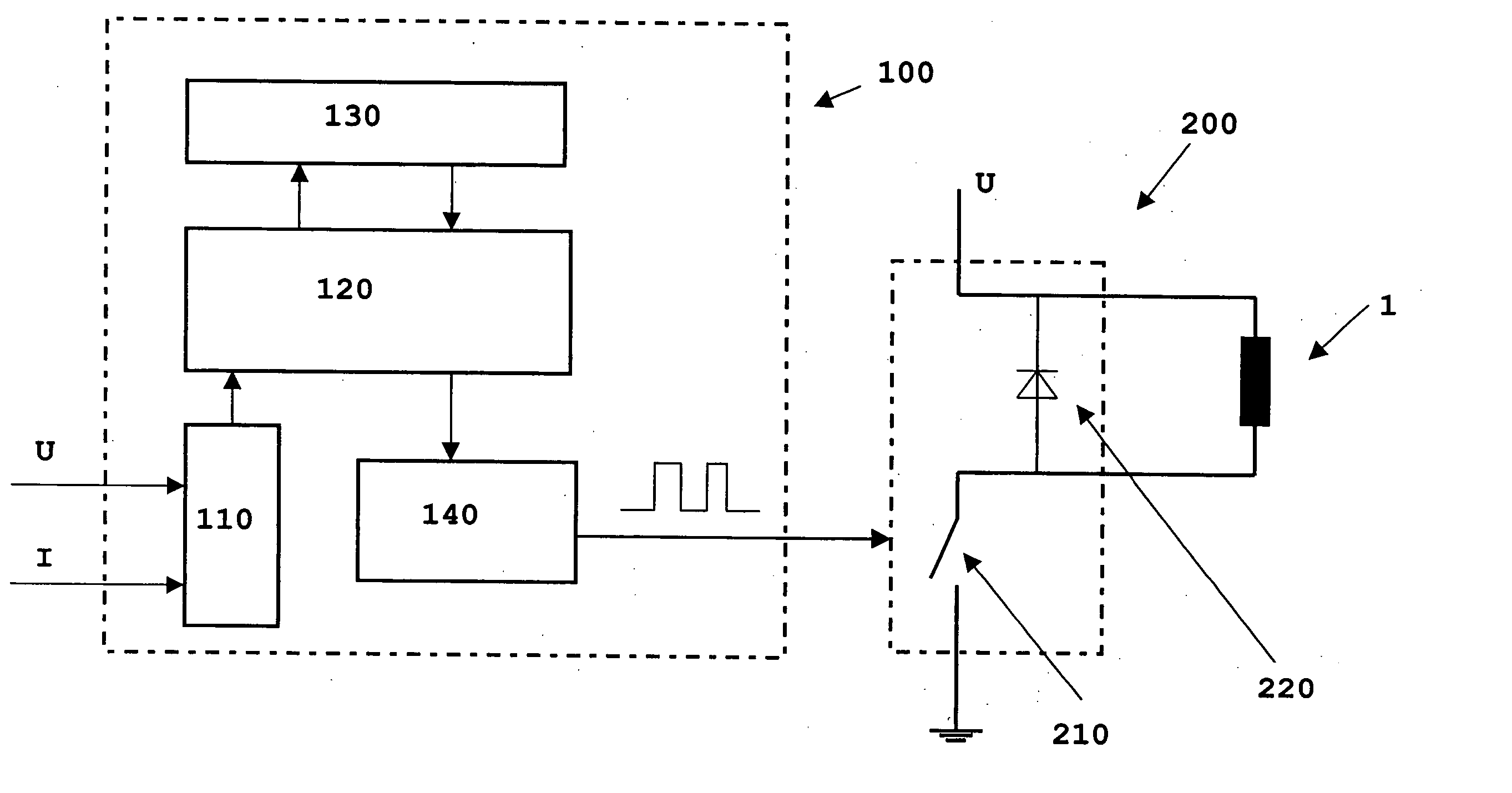
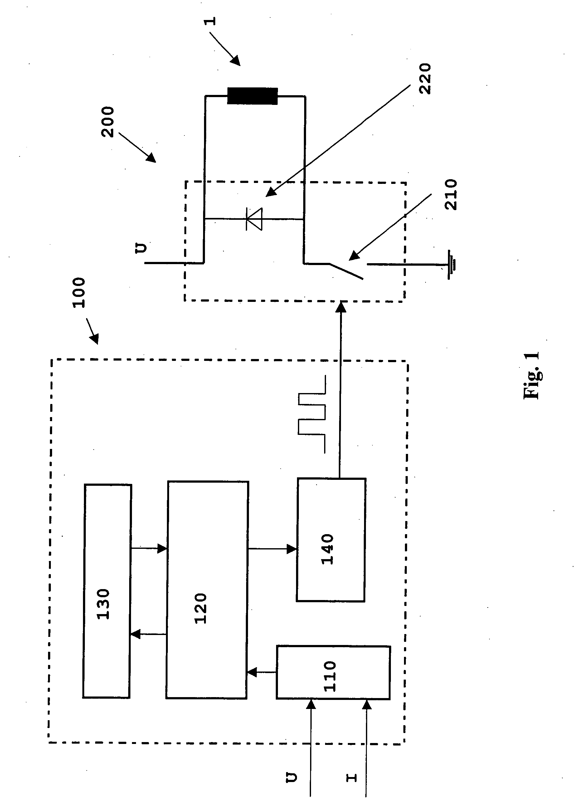
[0020]FIG. 1 shows a basic circuit diagram of a system according to the present invention having an inductive load of an adjusting device 1, a control unit 100 and an output stage 200. Current I and voltage U of adjusting device 1 are acquired via an analog / digital converter 110 and are transmitted to a microprocessor 120 having a control element 130. Following the evaluation of current and voltage, microprocessor 120 transmits suitable characteristic quantities to a modulator 140. Depending on the specific embodiment, suitable characteristic quantities are either ascertained directly from one or multiple measured values or suitable characteristic quantities are stored in control element 130 or in a so-called characteristics map. For an existing voltage, the corresponding characteristic quantities are then read out from a characteristics map. From the characteristic quantities, modulator 140 generates a pulsed signal, for example by pulse-width modulation, which is used to control a...


PUM


Abstract

A method for operating an inductive load, which is operated in a motor vehicle with electric voltages of different magnitudes, is provided, a current rise in the inductive load being influenced by selecting pulse lengths and pulse pauses of the electric voltage.

Description

FIELD OF THE INVENTION [0001] The present invention relates to a method for operating an inductive load with different electric voltages as well as an adjusting device and a control unit. BACKGROUND OF THE INVENTION [0002] In the area of engine management for gasoline and diesel engines, components representing an inductive load are frequently used such as quantity-control valves of high-pressure pumps or injection valves, for example. These components are typically triggered via a simple switch output stage. [0003] As a result of fluctuations in the vehicle system voltage, the components behave differently, depending on the vehicle system voltage currently available. This changes especially the metering behavior of valves, particularly of injection valves. It is possible to compensate for changes in the metering behavior caused by fluctuations in the vehicle system voltage for example by extending or shortening the triggering times of the affected components accordingly. Since the ...

Claims


Application Information

Patent Timeline
Patent Type & Authority Applications(United States)
IPC IPC(8): F04B49/22
CPCF04B49/225H01F7/1844H01F7/1811
Inventor FRENZ, THOMASECKHARDT, JUERGENSCHWARZ, HANS-FRIEDRICHSCHROEDER, BERNDHOLLMANN, TIMMKUEMPEL, JOERG
Owner ROBERT BOSCH GMBH
Why Eureka
Try Eureka