Method for starting an electronic drive circuit of an electric motor and circuit arrangement therefor

Active Publication Date: 2012-10-04
ANDREAS STIHL AG & CO KG
View PDF4 Cites 11 Cited by
  • Summary
  • Abstract
  • Description
  • Claims
  • Application Information

AI Technical Summary

Benefits of technology

[0005]It is an object of the invention to provide a method for starting an electronic drive circuit for the stator windings of an ele

Problems solved by technology

If such a battery pack is connected to a defective drive circuit, high currents can already flow while the motor

Method used


Image

  • Method for starting an electronic drive circuit of an electric motor and circuit arrangement therefor
  • Method for starting an electronic drive circuit of an electric motor and circuit arrangement therefor
  • Method for starting an electronic drive circuit of an electric motor and circuit arrangement therefor

Examples


Embodiment Construction

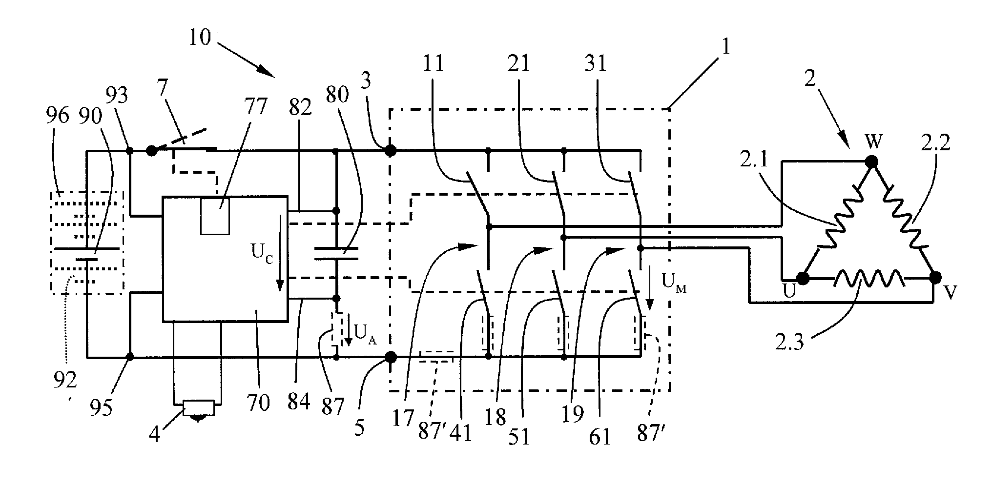
[0025]The circuit arrangement 10 schematically shown in FIG. 1 serves to start an electronic drive circuit 1 for the stator windings 2.1, 2.2 and 2.3 of an electric motor 2. In the exemplary embodiment shown, the electric motor is an electronically commutated motor, a so-called EC-motor with windings 2.1, 2.2 and 2.3, in particular the windings of the stator, connected in a delta connection. Alternatively, a star connection of the windings is possible. The drive circuit 1 is also suitable in a corresponding manner for driving direct current motors, synchronous motors, asynchronous motors or the like.

[0026]The drive circuit 1 is connected to the connecting terminals 93 and 95 of a voltage source 90 by way of its input terminals 3 and 5. The voltage source 90 is a direct current source, the voltage of which is transmitted further by the drive circuit 1 as a pulsewidth modulated signal. A capacitor 80 for cancelling voltage peaks, especially an electrolytic capacitor, is connected in p...


PUM


Abstract

The invention relates to a method for starting an electronic drive circuit for the windings of an electric motor. A control unit, which is connected to a voltage source, is provided as well as a capacitor connected via a system switch element to the connecting terminals of the voltage source. The capacitor is connected across the input terminals parallel to the drive circuit. An operating circuit controls the system switch element. In order to start the motor, the operating circuit closes the system switch element and charges the capacitor and after the charging of the capacitor, opens the system switch element again. A test step is then started by the control unit, the drive circuit being supplied exclusively by the capacitor voltage (UC) during the test step.

Description

CROSS REFERENCE TO RELATED APPLICATION[0001]This application claims priority of German patent application no. 10 2011 015 977.0, filed Apr. 4, 2011, the entire content of which is incorporated herein by reference.FIELD OF THE INVENTION[0002]The invention relates to a method for starting an electronic drive circuit for a stator winding of an electric motor and a circuit arrangement therefor.BACKGROUND OF THE INVENTION[0003]It is known to connect an electric motor such as an electronically commutated EC-motor or the like to a DC-voltage source via a control circuit or inverter, wherein the coil ends of the stator windings are each connected via a power switch to the one connecting terminal of the voltage source and via a further power switch to the other connecting terminal of the voltage source. The control unit switches the six power switches in such a manner that a rotating field results for the rotor in the stator of the motor and entrains the rotor.[0004]In a handheld electric wo...

Claims


Application Information

Patent Timeline
IPC IPC(8): H02P1/16
CPCH02P29/028H02P29/021H02P29/032H02P29/0241G01R31/34
Inventor WICHERT, RENELIEBHARD, GERNOT
Owner ANDREAS STIHL AG & CO KG
Why Eureka
Try Eureka