Fuel cutoff valve

a technology of fuel cutoff valve and cutoff valve body, which is applied in the direction of valve operating means/release devices, functional valve types, containers, etc., can solve the problems of variable cutoff fuel level, float molding precision suffers, and the buoyancy of the float is affected, so as to improve the molding precision of the float, reduce the variability of the cutoff fuel level, and improve the effect of manufacturability

Active Publication Date: 2009-08-11
TOYODA GOSEI CO LTD +1
View PDF12 Cites 23 Cited by
  • Summary
  • Abstract
  • Description
  • Claims
  • Application Information

AI Technical Summary

Benefits of technology

[0007]An advantage of some aspects of the invention is to provide a fuel cut off valve that reduces variability in the cutoff fuel level due to variation in temperature within the fuel tank and improves the molding precision of the float while providing superior manufacturability.
[0009]In a fuel tank that uses a fuel cutoff valve according to the present invention, when fuel is provided into said fuel tank so that the fuel reaches a predetermined level in the fuel tank, the float mechanism is raised by a buoyant force, caused by the fuel that has flowed into the valve chamber, so that the valve portion closes the connection conduit, cutting off the fuel tank from the outside, thereby preventing fuel from flowing from the fuel tank to the outside.
[0010]The float mechanism is a mechanism with a plurality of members, comprising a first float body and a second float body, or in other words, the wall thickness of the first float body can be made thinner by using a structure wherein the second float body fills the storage chamber of the cup-shaped first float body. Doing so makes it possible to reduce the shrinkage in the valve portion, or the like, of the first float body, making it possible to increase the mold efficiency, when fabricating the first float body using injection molding. Moreover, by having the first float body be cup-shaped, the storage chamber of the first float body, which opens in the downwards direction, is filled by the second float body, making it possible to reduce the volume of vapor that enters therein, making it possible to reduce the variation in the cutoff fuel level by eliminating the variations in the buoyant force of the float mechanism accompanying changes in the temperature of the vapor.
[0011]Furthermore, because the storage chamber in the first float body is large, cooling means can be provided in the mold for fabricating the storage chamber when the float mechanism is fabricated through resin injection molding, and the second float body may be a member small enough to fill the storage chamber, so cooling of both members will not require extended time intervals. Consequently, it is possible to reduce the length of the fabrication cycle in injection molding, with superior manufacturability.
[0012]Since the first float body and the second float body can be structured so as to be integrated by a fitting means comprising an engaging claw and a fitting hole, this structure makes it possible to reduce the amount of work in assembling the first float body and the second float body.
[0014]Since the top part of said storage chamber may be structured so as to connect to the outside of said float mechanism through a vent that is formed through said first float body, this makes it possible to reduce variations in the valve closing position through reducing variations in the buoyant force of the float mechanism accompanying changes in temperature of the vapor, because the storage chamber is not vapor-tight.

Problems solved by technology

The vapor in the sealed buoyancy chamber expands and contracts depending on changes in the temperature within the fuel tank, causing variability in the buoyancy of the float.
Because of this, the fuel cutoff valve has a problem in that the cutoff fuel level will vary depending on changes in temperature within the fuel tank.
When the buoyancy chamber is reduced in size in order to solve this problem, then not only does the molding precision of the float suffer due to shrinkage in the resin at the time of injection molding, but there is an additional problem in that this also causes a reduction in productivity due to the increased time required for cooling.

Method used


Image

  • Fuel cutoff valve
  • Fuel cutoff valve
  • Fuel cutoff valve

Examples


first embodiment

A. First Embodiment

[0037](1) Schematic Structure of Fuel Cutoff Valve 10

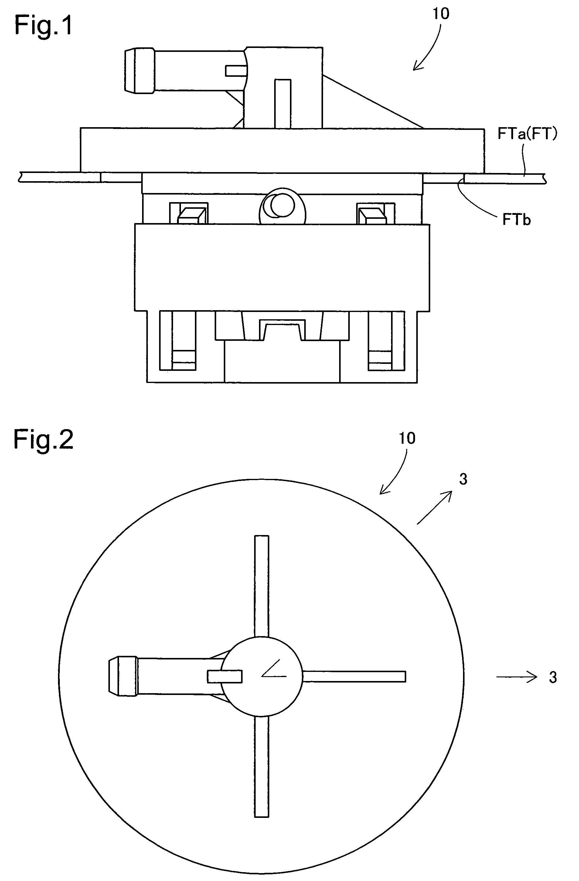
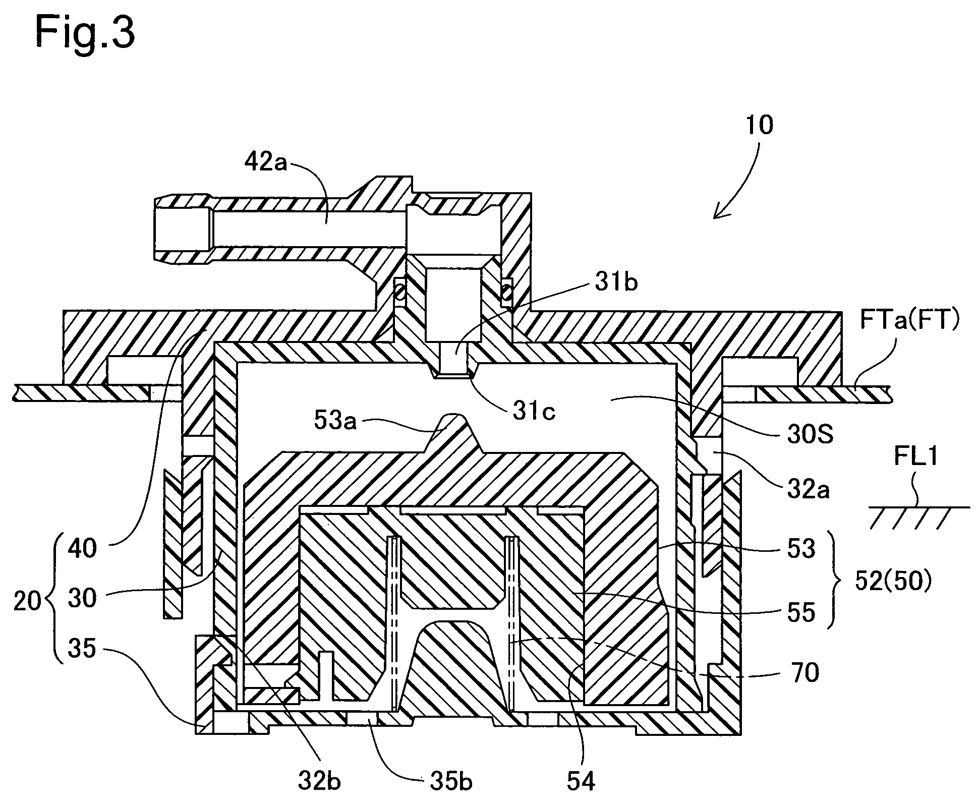
[0038]FIG. 1 is a side view illustrating a fuel cutoff valve 10, attached at the top part of an automobile fuel tank FT, according to an embodiment of the present invention; FIG. 2 is a plan view of the fuel cutoff valve 10; and FIG. 3 is a cross-sectional view along the section 3-3 in FIG. 2. In FIG. 1, the fuel tank FT is fabricated from a compound resin material that includes polyethylene on the surface thereof, structured with an attachment hole FTb at the tank upper wall FTa. The fuel cutoff valve 10 is attached to the tank upper wall FTa in a state wherein the lower part of the fuel cutoff valve 10 is inserted into the attachment hole FTb. The fuel cutoff valve 10 prevents the flow of fuel from the fuel tank FT into the canister when the vehicle is at an angle in the pitch or roll direction.[0039](2) Structure of Each Part of the Fuel Cutoff Valve 10

[0040]In FIG. 3, the fuel cutoff valve 10 is provided wit...

second embodiment

B. Second Embodiment

[0052](1) Schematic Structure of Fuel Cutoff Valve 100

[0053]The fuel cutoff valve in the second embodiment has an auto-stop function along with preventing the flow of fuel within the fuel tank into the canister during fueling until a predetermined level has been reached, and also prevents overfill. FIG. 6 is a cross-sectional view of a fuel cutoff valve 100. The fuel cutoff valve 100 comprises a casing 120, a float mechanism 150, and a spring 170 as the primary structures thereof. The casing 120 is provided with a casing main body 130, a bottom plate 135, and a cover 140, where the space surrounded by the casing main body 130 and the bottom plate 135 forms a valve chamber 130S, where the float mechanism 150, supported by a spring 170, is housed in the valve chamber 130S.[0054](2) Structure of Each Part of the Fuel Cutoff Valve 100

[0055]FIG. 7 is a cross-sectional view of the assembly of the fuel cutoff valve 100. The casing main body 130 is cup-shaped, surrounded...

third embodiment

C. Third Embodiment

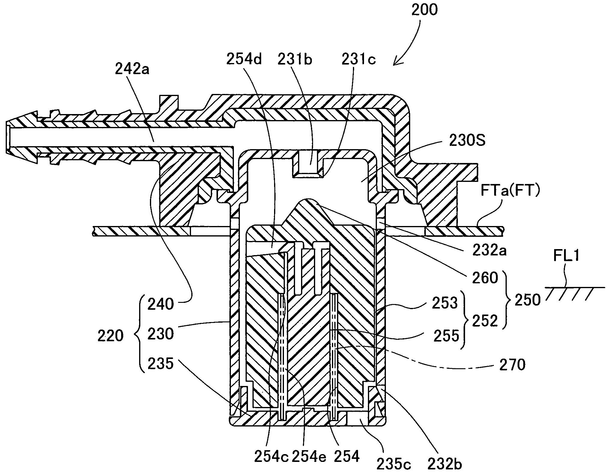
[0070](1) Structure of A Fuel Cutoff Valve 200

[0071]FIG. 12 is a side view illustrating a fuel cutoff valve 200, equipped at the top part of a fuel tank FT of an automobile, according to a third embodiment according to the present invention, FIG. 13 is a plan view of the fuel cutoff valve 200, and FIG. 14 is a cross-sectional view along the section 14-14 in FIG. 13. The fuel cutoff valve 200 prevents the fuel inside of the fuel tank FT from flowing out to the canister when the automobile is at an angle in the pitch or roll direction.

[0072]In FIG. 14, the fuel cutoff valve 200 is provided with a casing 220, a float mechanism 250, and a spring 270 as the main structural components thereof. The casing 220 is provided with a casing main body 230, a bottom plate 235, and a cover 240, where the space surrounded by the casing main body 230 and the bottom plate 235 forms a valve chamber 230S, where a float mechanism 250, supported on a spring 270, is housed in the valve c...


PUM


Abstract

A fuel cutoff valve is provided with a casing that forms a valve chamber that is connected to a connection conduit, a float mechanism that is housed so as to be able to rise and fall in the valve chamber, and a spring that supports the float mechanism. The float mechanism is structured through an assembly of a first float body and a second float body, where the first float body is provided with a valve portion that opens and closes the connection conduit and provided with a storage chamber that is open on the bottom, where the second float body is housed in the storage chamber to be assembled into the first float body.

Description

[0001]This application claims the benefit of and priority from Japanese Application No. 2005-220457 filed Jul. 29, 2005, the content of which is incorporated herein by reference.BACKGROUND OF THE INVENTION[0002]1. Field of the Invention[0003]The present invention relates to a fuel cutoff valve mounted on an upper wall of a fuel tank to open and close a connection conduit, which connects the inside of the fuel tank with the outside.[0004]2. Description of the Related Art[0005]Conventional fuel cutoff valves have been known in JP-A-2004-308838, and JU-A-5-1547. The fuel cutoff valve is mounted on the upper wall of a fuel tank, and comprises a casing with a connection conduit that connects to the outside (the canister) and a float that rises and falls with changes in the buoyant force according to the fuel level within a valve chamber of the casing. The fuel cutoff valve closes the connection conduit by the float rising due to an increase in buoyant force due to an increase in the fuel...

Claims


Application Information

Patent Timeline
Patent Type & Authority Patents(United States)
IPC IPC(8): F16K24/04B60K15/035F16K31/18
CPCF16K24/044B60K15/03519Y10T137/7426Y10T137/3099Y10T137/0874
Inventor KANEKO, KENICHIROKITO, HIROAKINISHI, HIROSHIUHARA, SHOJIWATANABE, HIDEOHASEGAWA, YASUHIRO
Owner TOYODA GOSEI CO LTD
Why Eureka
Try Eureka