Computer hologram and creation method thereof

a computer and hologram technology, applied in the field of hologram creation methods, can solve problems such as problems such as problems to be solved, grayscale image reproduction quality decline, so as to achieve clearer reproduction images and reduce unnecessary noise components

Active Publication Date: 2009-08-11
DAI NIPPON PRINTING CO LTD
View PDF6 Cites 8 Cited by
  • Summary
  • Abstract
  • Description
  • Claims
  • Application Information

AI Technical Summary

Benefits of technology

[0038]By a creation method of a computer hologram according to the present invention, since an unnecessary noise component generated during observation can be reduced, it becomes possible to obtain a clearer reproduced image.

Problems solved by technology

As described above, computer holograms are a field for which great demand is expected in the future, however, at this time, there are some problems to be solved in realizing commercial use.
One of the great challenges is to enable reproduction of a high-quality grayscale image.
A computer hologram created by a conventional method has a problem in that reproduction quality of a grayscale image declines in comparison with an optical hologram.
However, a phenomenon that unnecessary noise components are overlapped is recognized in a reproduced image, and it is undeniable that, in comparison with a hologram created by an optical method, reproduction quality of a grayscale image declines.
Particularly, in the lighting environment of the real world where a multiple of light sources exist, a reproduced image is observed in a condition mixed with a large number of noise components, and visibility cannot but decline in comparison with an optical hologram.

Method used


Image

  • Computer hologram and creation method thereof
  • Computer hologram and creation method thereof
  • Computer hologram and creation method thereof

Examples


Embodiment Construction

[0057]Hereinafter, the present invention will be described based on illustrated embodiments.

>>

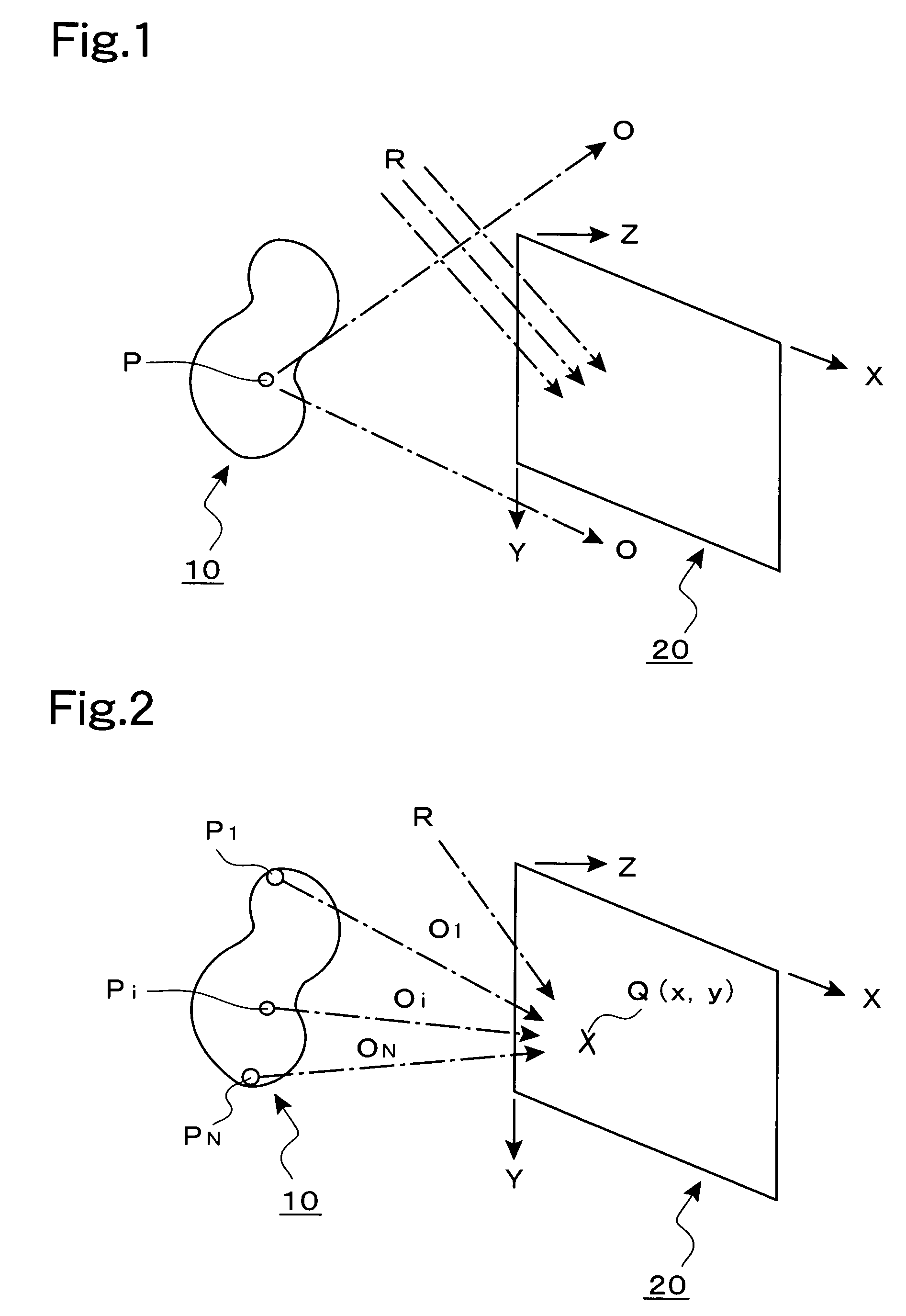
[0058]FIG. 1 is a principle diagram showing a general hologram creation method, in which a method for recording an original image 10 on a recording surface 20 as interference fringes is shown. Here, for convenience of description, an XYZ three-dimensional coordinate system is defined as illustrated, and the recording surface 20 is placed on an XY plane. When an optical method is employed, an object to be a recording target is to be prepared as the original image 10. An object light O emitted from an arbitrary point P on the original image 10 proceeds toward the entire surface of the recording surface 20. On the other hand, a reference light R has been irradiated onto the recording surface 20, and interference fringes of the object light O and reference light R are recorded on the recording surface 20.

[0059]In order to create a computer hologram at the position of the recording surface 20, t...


PUM


Abstract

An original image (10), a recording surface (20), and a reference light (R) are defined and a large number of calculation points (Q(x, y)) are defined at a predetermined pitch on the recording surface (20). For each of the calculation points, intensity of interference wave, formed by an object light (O1 to ON) generated from the respective parts (P1 to PN) of the original image (10) and a reference light (R), is calculated. A binary pattern defined by dividing a unit area into a first area having a pixel value “white” and a second area having a pixel value “black” is defined in a plurality of ways by changing the occupancy ratio (0 to 100%) of the first area. A binary pattern having the occupancy ratio corresponding to the interference wave intensity calculated, is assigned to the position of the respective calculation points (Q) on the recording surface (20) so as to form a binary image and create a computer hologram medium having convex and concave portions. By setting the vertical and horizontal pitched of the calculation points (Q) to 400 nm or below, it is possible to reduce the unnecessary noise component generated during observation and obtain a clear reproduction area.

Description

TECHNICAL FIELD[0001]The present invention relates to a hologram creation method, and more particularly, to a creation method of a computer hologram created by forming interference fringes on a predetermined recording surface by a computer-aided operation.BACKGROUND ART[0002]In recent years, it has become possible to easily obtain a coherent light by use of a laser, and commercial use of holograms has also become considerably widespread. Particularly, for exchange tickets for money and credit cards, from an anticounterfeit standpoint, it has been generalized to create a hologram at a part of the medium.[0003]Currently, most of the commercially used holograms are ones created by recording an original image on a medium as interference fringes by an optical method. That is, in the optical method employed, an object from which an original image is formed is prepared, light from the object and reference light are led onto a recording surface applied with a photosensitive material by use ...

Claims


Application Information

Patent Timeline
Patent Type & Authority Patents(United States)
IPC IPC(8): G03H1/08G03H1/18
CPCG03H1/08G03H1/0841G03H2240/41G03H2240/13
Inventor KITAMURA, MITSURU
Owner DAI NIPPON PRINTING CO LTD
Why Eureka
Try Eureka