Configurations and methods for power generation with integrated LNG regasification

a technology of lng regasification and power generation, which is applied in the direction of positive displacement engines, mechanical equipment, machines/engines, etc., can solve the problems of limited heat transfer in some configurations, reduced natural gas supplies in the domestic market, and relatively energy-intensive lng vaporization process, so as to achieve the effect of increasing power generation

Inactive Publication Date: 2009-08-18
FLUOR TECH CORP
View PDF16 Cites 124 Cited by
  • Summary
  • Abstract
  • Description
  • Claims
  • Application Information

AI Technical Summary

Problems solved by technology

However, domestic supplies of natural gas are beginning to diminish due to increasing demand from industrial, residential, and / or electric utilities consumers.
LNG vaporization is a relatively energy intensive process and typically requires heating energy of about 3% of the energy content in LNG.
Still further, and among yet other difficulties, the heat transfer in some of these configurations is limited by the freezing point of the heat transfer medium.
Moreover, while the refrigeration content of the LNG is utilized to at least some degree, electric or other power is not extracted from such configurations.
While such a configuration increases efficiency of a plant to at least some degree, several problems remain.
However, the operation of such batch system is difficult and complex.
Moreover, most of such Rankine cycle processes fail to utilize the full temperature range in LNG regasification.
While such conceptually relatively simple processes provide at least some energy from the LNG cold, various disadvantages similar to those provided above remain.
However, such configurations are typically limited to LNG processing with nominal power generation requirement and fail to lend themselves to full utilization of the LNG cold in power generation in LNG regasification facilities.
Therefore, while numerous processes and configurations for LNG utilization and regasification are known in the art, all of almost all of them suffer from one or more disadvantages.

Method used


Image

  • Configurations and methods for power generation with integrated LNG regasification
  • Configurations and methods for power generation with integrated LNG regasification
  • Configurations and methods for power generation with integrated LNG regasification

Examples


Embodiment Construction

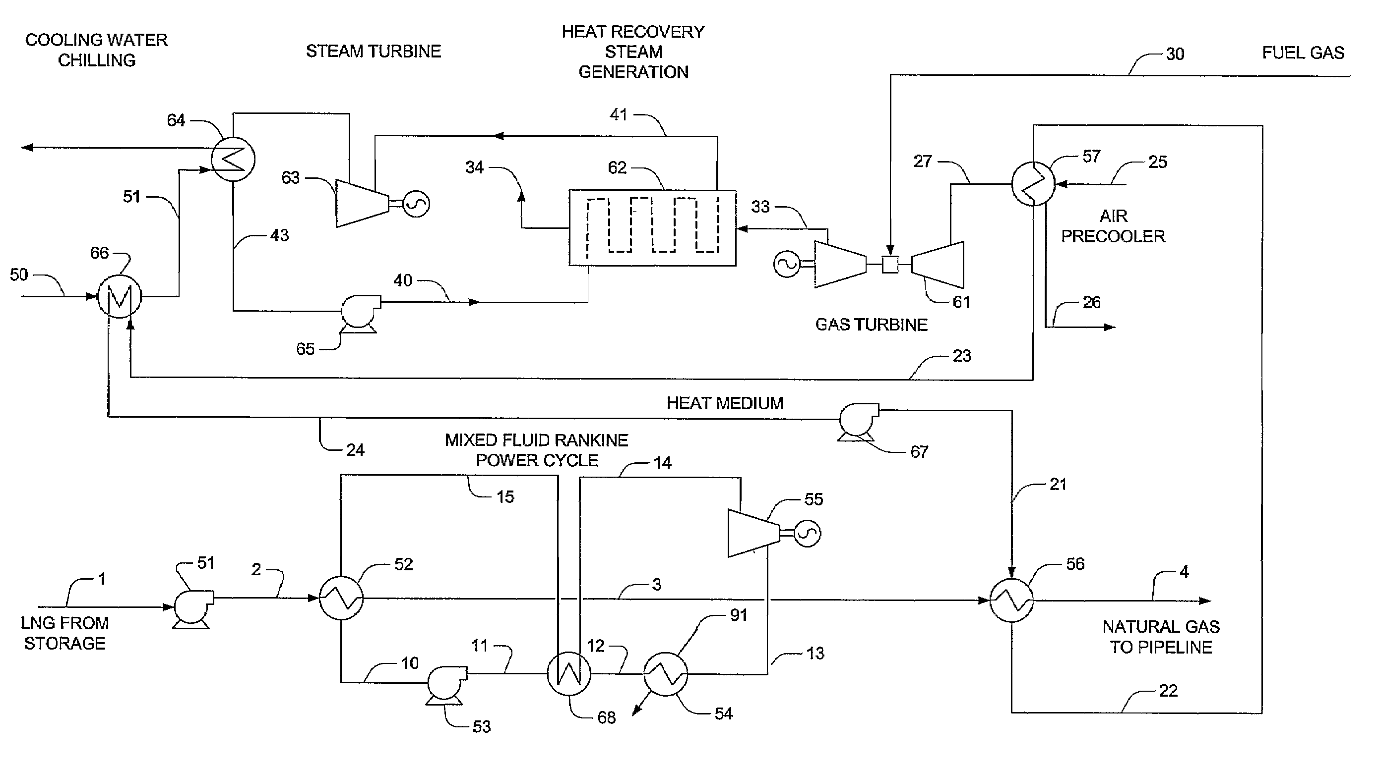
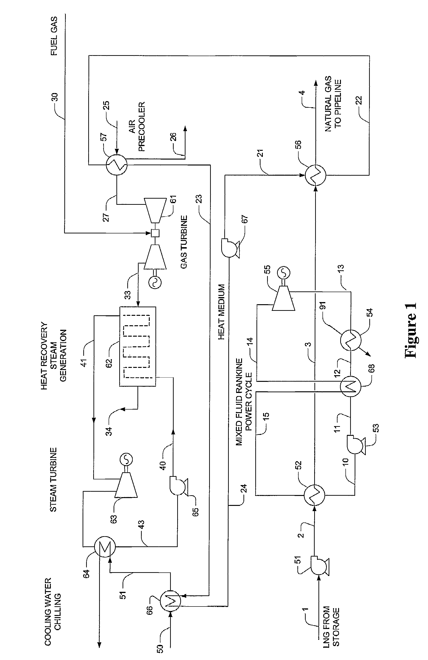
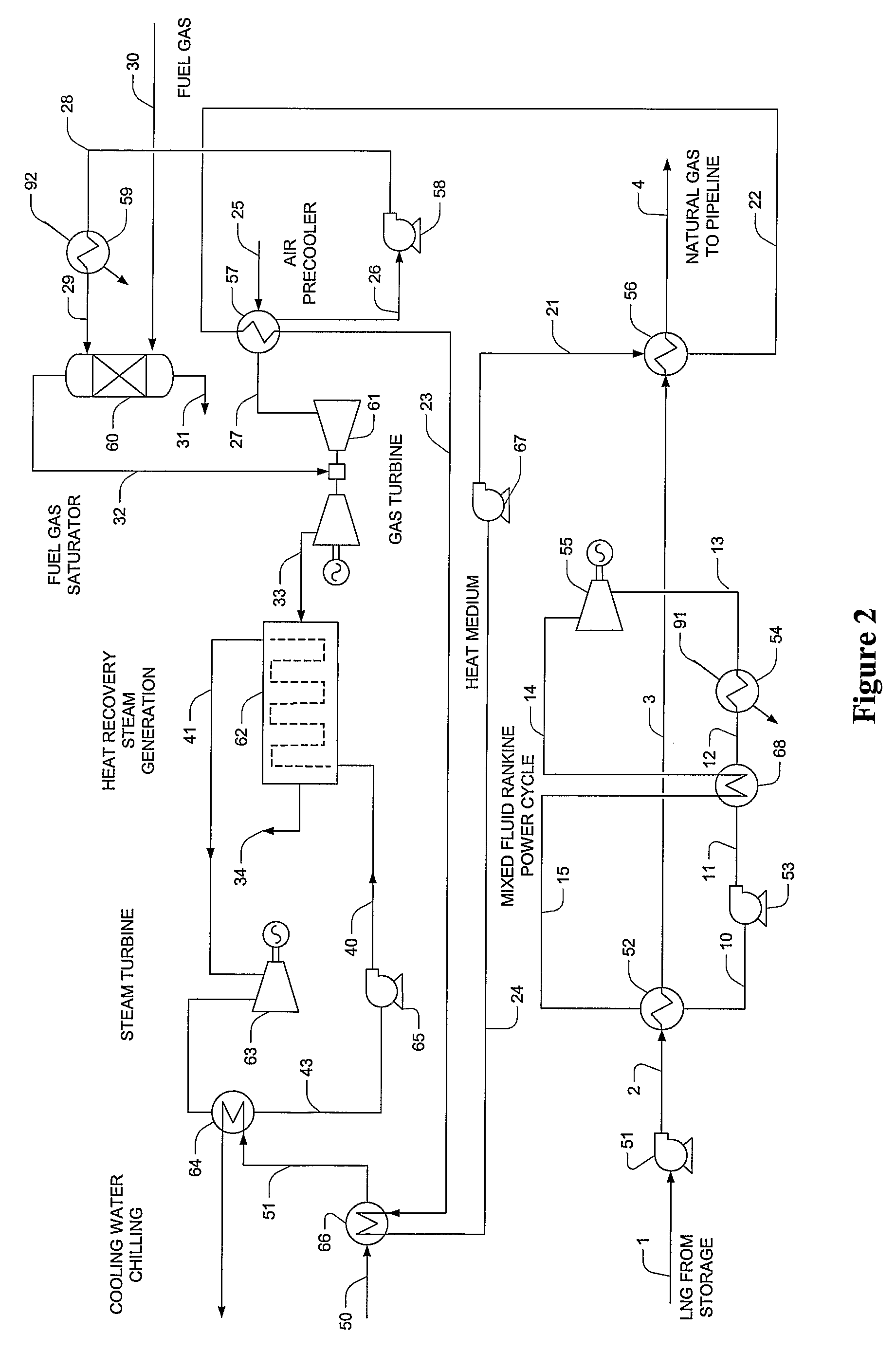
[0021]The inventor has discovered that the refrigeration content in LNG can be effectively used for power generation in a process that delivers vaporized LNG (most preferably, the vaporized LNG is delivered at pipeline pressure), wherein power is generated and / or power generation is increased at multiple points in a plant. In particularly preferred aspects, the plant combines a combustion turbine generator and heat recovery steam generator with an LNG regasification unit, wherein the combustion turbine may be driven by combustion of a portion of the gasified LNG.

[0022]In especially preferred plant configurations, power is produced in a first stage using a Rankine power cycle, wherein the working fluid typically comprises a multi-component fluid mixture to optimize use of the cryogenic temperature of the LNG (preferably in the range of about −250° F. to −50° F.). Alternatively, LNG may also be used in an open Rankine power cycle in the first stage, thereby eliminating the use of an e...


PUM


Abstract

LNG cold is used in a plurality of cycles in a combined power plant to increase power output. Especially preferred plant configurations integrate a combined cycle power plant with a regasification operation in which in a first stage LNG cold provides cooling in an open or closed power cycle. Most preferably, a significant portion of the LNG is vaporized in the first stage. In a second stage LNG cold provides cooling for a heat transfer medium that is used to provide refrigeration for the cooling water to a steam power turbine and for an air intake chiller of a combustion turbine in the power plant.

Description

[0001]This application claims the benefit of our U.S. provisional patent application with the Ser. No. 60 / 588,275, filed Jul. 14, 2004, and which is incorporated by reference herein.FIELD OF THE INVENTION[0002]The field of the invention is power generation using Liquefied Natural Gas (LNG), and especially as it relates to power generation in LNG regasification facilities, and / or integration to a combined cycle power plant.BACKGROUND OF THE INVENTION[0003]While the US has imported crude oil as energy carrier for several decades, natural gas demand has mostly been met from domestic supplies. However, domestic supplies of natural gas are beginning to diminish due to increasing demand from industrial, residential, and / or electric utilities consumers. This situation is further compounded by the replacement of older power plants with new “clean-burning” natural gas power plants. Consequently, LNG import has become economically increasingly attractive, and existing LNG regasification facil...

Claims


Application Information

Patent Timeline
Patent Type & Authority Patents(United States)
IPC IPC(8): F02C6/00
CPCF01K23/10F01K25/06Y02E20/16F17C2270/05F17C2265/05
Inventor MAK, JOHN
Owner FLUOR TECH CORP
Why Eureka
Try Eureka