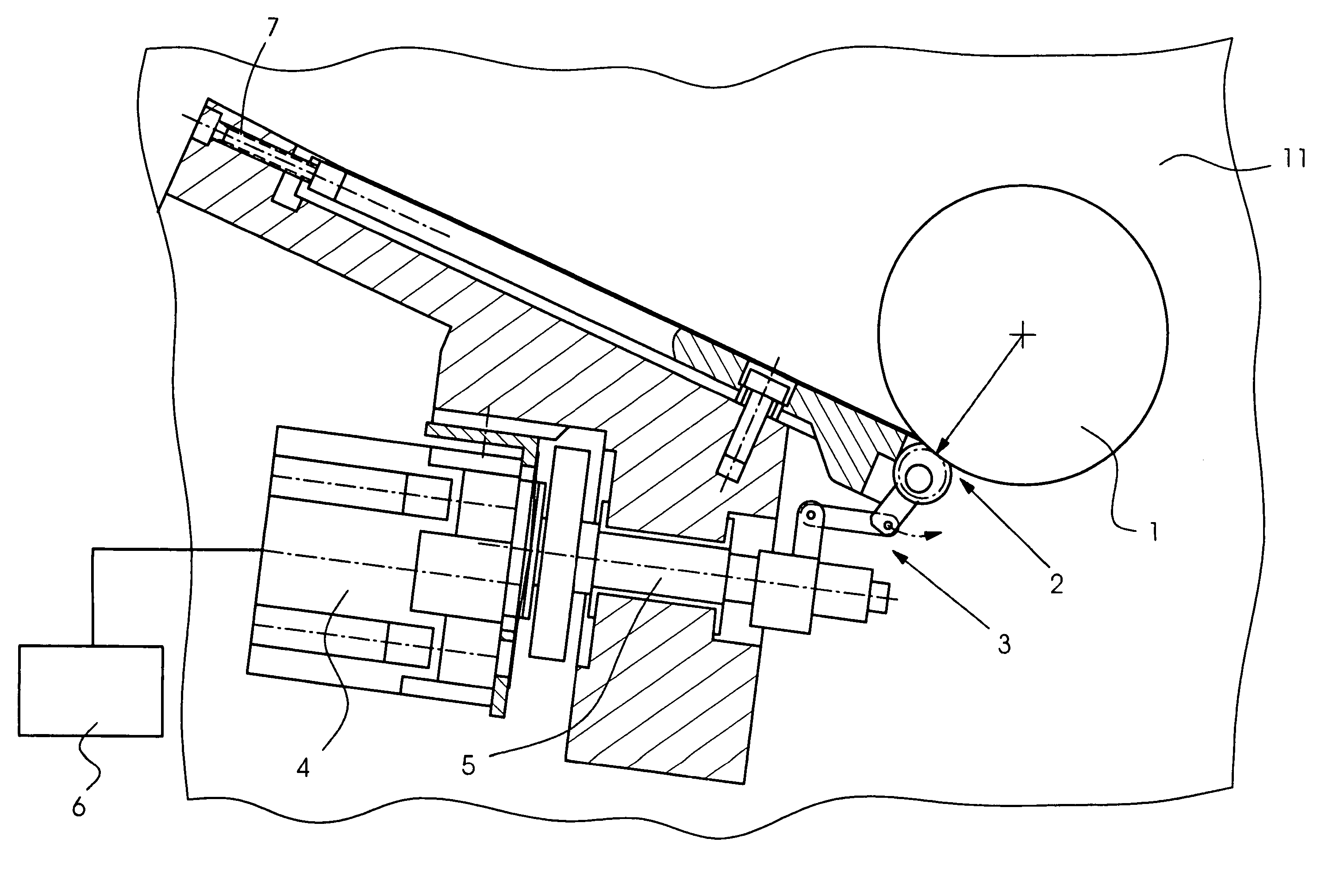
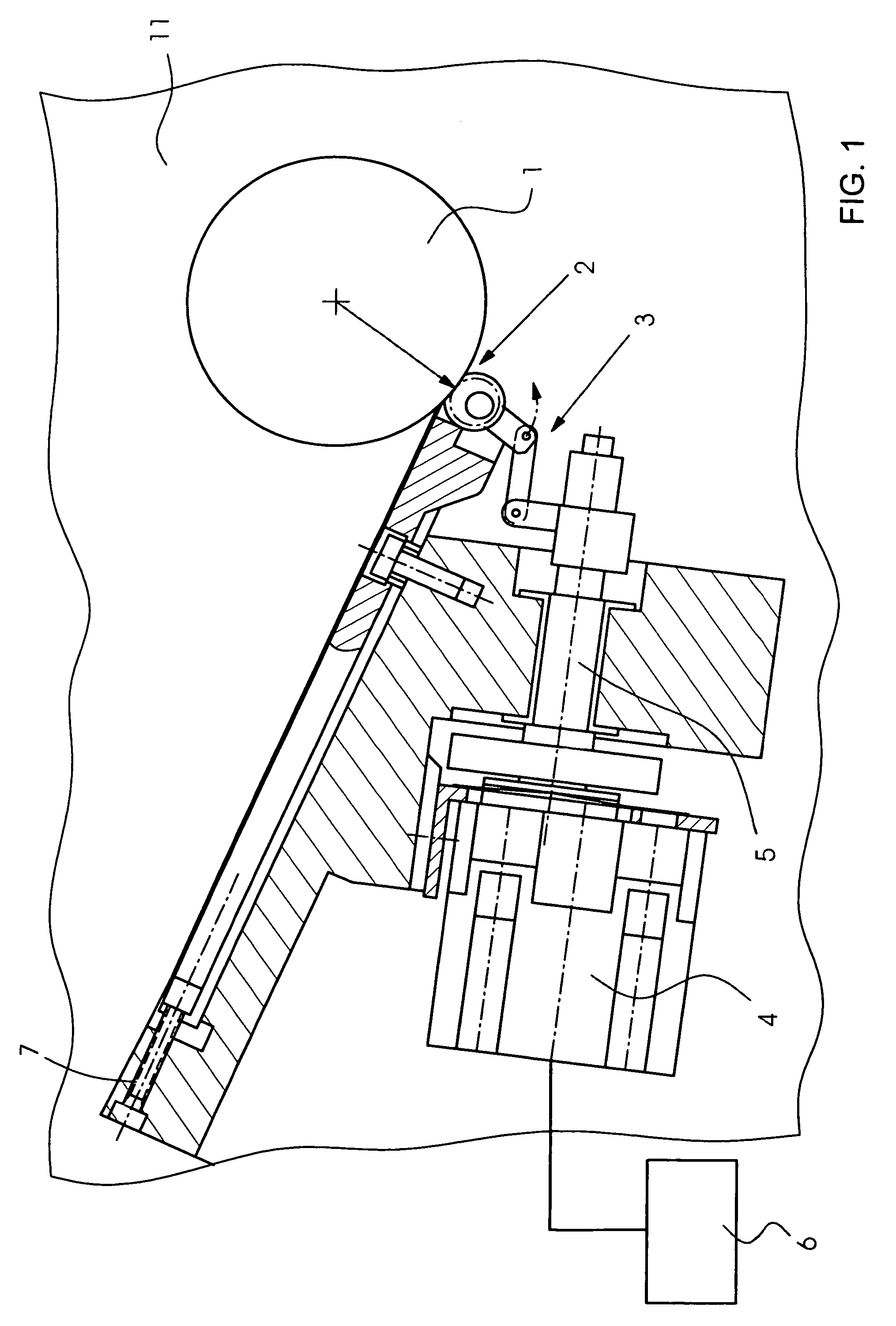
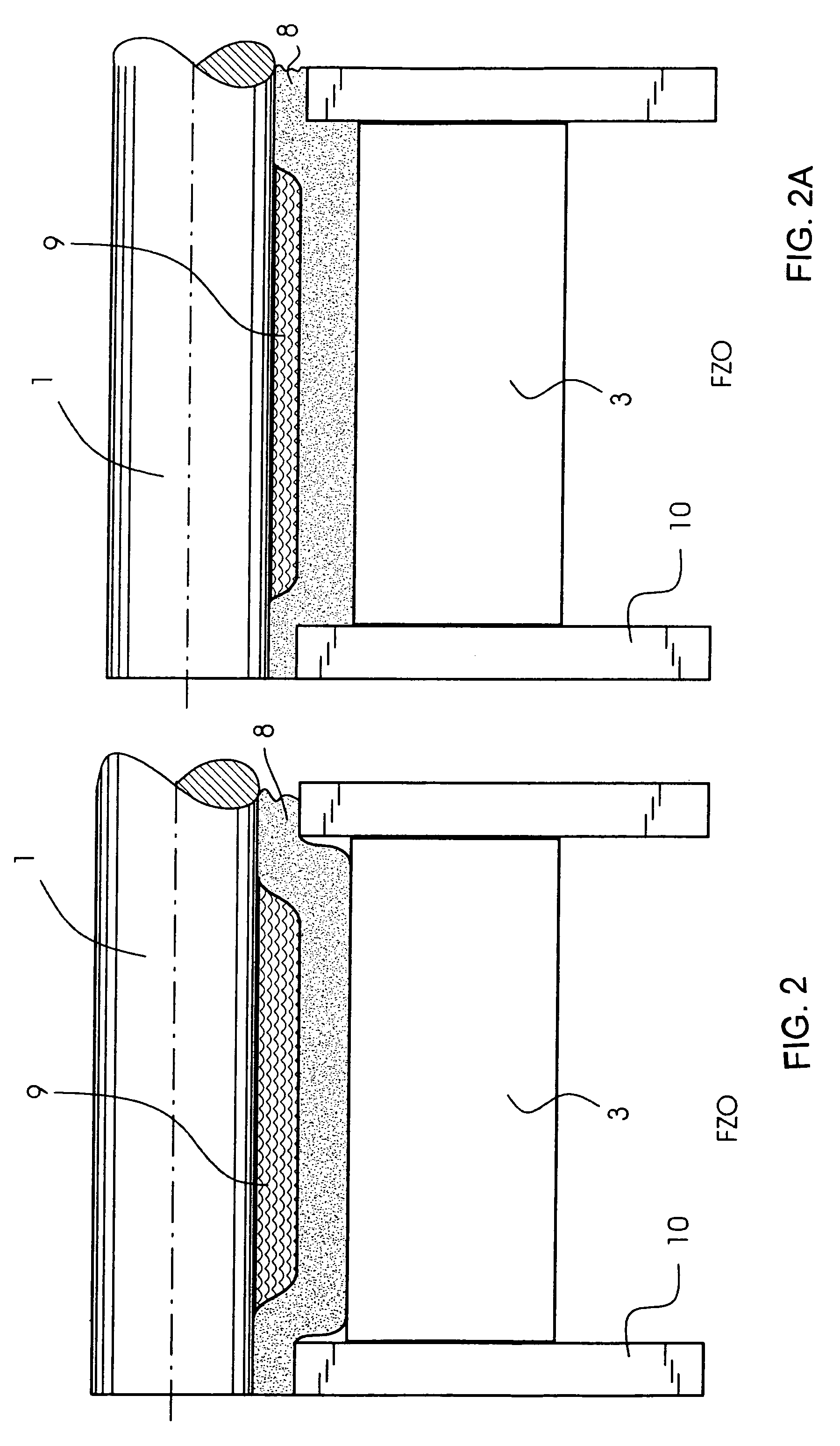
[0008]With the present invention, it is possible for the first time to register the wear of an ink fountain film during the operation of a printing press. The invention can be employed in all offset printing presses having ink fountains in which zonal ink metering is carried out by ink metering elements operating against a ductor roller. Between the ductor roller and ink metering elements there is a replaceable ink fountain film, in order to avoid damage to the ink doctor roller and the ink metering elements. The ink metering elements can be moved in the direction of the ductor by an electric, hydraulic or pneumatic drive, so that the distance between ink metering elements and ink ductor can be set as desired by the drive. When the ink fountain film is located in the ink fountain, the distance between the ink fountain film and ink ductor can also be determined by the drive element. The wear of the ink fountain film can be read off by using the remaining thickness of the film. If the thickness of the ink fountain film falls below a permissible amount, it counts as used, since there is then the risk that the ink fountain film will wear through and in this way ink ductor and ink metering elements can come directly into contact. In order to register the thickness of the ink fountain film, first the closed position of the one or of the plurality of ink metering elements is determined with the ink fountain film inserted. To this end, at least one metering element is closed until it is just pressing the film against the ductor roller. This position of the ink metering element is called the closed position. The closed position determined in this way is registered by a sensor and stored on a computer of the printing press. During the operation of the printing press, the closed position is then monitored continuously, so that deviations from the stored closed position can be registered.
[0009]If the deviations from the closed position determined at first exceed a permitted amount, it can be assumed that the ink fountain film has suffered excessive abrasion in accordance with the deviations, and has thus reached the dangerous region. It is therefore possible for the sensor to monitor the remaining thickness and thus the wear of the ink fountain film continuously during the operation of the printing press. The operating personnel therefore no longer have to carry out a visual inspection in the ink fountain at regular intervals in order to monitor whether the ink fountain film still has sufficient material. In addition, in the case of a defective ink fountain film which, because of a lower quality, wears more quickly than generally usual, a collision of the ink metering element with the ductor can be prevented. The present invention thus permits reliable and mechanical monitoring of the wear of the ink fountain film.
[0012]In a particularly advantageous refinement of the invention, provision is made that when the thickness of the ink fountain film falls below a predefined value, a warning signal is generated. In addition to or instead of the visual display of the state of the ink fountain film on a monitor, an acoustic or additional visual warning signal in the form of a flashing light can also be output when the thickness of the ink fountain film has fallen below the minimum permissible. An acoustic warning signal has the advantage that the operating personnel are informed about the state of the ink fountain film even if they are not within the visual range of the monitor but, for example, are carrying out maintenance work or changeover work on a remote part of the printing press.
[0014]Provision is additionally made for there to be a plurality of inking zones with a plurality of ink metering elements and for it to be possible to determine the current thickness of the ink fountain film separately for each of these inking zones. In this case, each ink metering element is monitored by a sensor, so that the thickness of the ink fountain film is determined over the entire width in all the inking zones. This has the advantage that different local wear of the ink fountain film can be registered, it then being possible to select as a measure that inking zone which exhibits the currently lowest still remaining residual thickness of the ink fountain film. When the inking zone then falls below the permitted minimum, the warning signal is output, so that the ink fountain film is replaced in good time. As compared with the solution with only one or a few sensors, it is therefore ensured that even locally disproportionately high wear of the ink fountain film is determined in good time, so that none of the ink metering elements wears through the ink fountain film in any inking zone and is able to strike the ink ductor.
[0016]Furthermore, it is alternatively or additionally possible for the rotational speed of the drive motor to be registered in order to register the closing point of the ink metering element. Via the rotational speed of the motor, the speed curve and, derived from the latter, the travel during the adjustment of the ink metering elements can be determined. As soon as the ink metering element strikes the ductor as it is being closed, the motor rotational speed decreases, since an increased resistance occurs. The closing point has thus been reached. This speed curve may be output to the computer by the rotational speed sensor present in most electric motors. In this case, no additional sensor is necessary, so that the result is a particularly economical solution.
[0017]Additionally, provision is made for the metering gap between the ink metering element and the ink ductor additionally to be adjustable by an adjusting element. The ink metering element is normally spring-mounted, so that even when the ink metering element strikes the ductor, a specific force is not exceeded, in order to avoid severe damage. In order to be able to shorten or lengthen the actuating travel of the ink metering element, the adjusting element is provided, with which the ink metering element, in its end position in the open state, can be positioned closer to or further away from the ductor. Such an adjusting element can constitute a screw, for example, which can be set in accordance with the desired distance.

