Check patentability & draft patents in minutes with Patsnap Eureka AI!

Backlight module with buffering protrusions and liquid crystal display with same

a backlight module and protruding technology, which is applied in the direction of lighting and heating apparatus, lighting device details, instruments, etc., can solve the problems of affecting the optical performance and reliability of the liquid crystal display b>1/b>, and affecting the quality of the imag

Inactive Publication Date: 2009-08-18
INNOLUX CORP
View PDF4 Cites 0 Cited by
  • Summary
  • Abstract
  • Description
  • Claims
  • Application Information

AI Technical Summary

Problems solved by technology

Liquid crystal displays are commonly used as display devices for compact electronic apparatuses, because they not only provide good quality images but are also very thin.
When this happens, components such as the liquid crystal panel 50 and the light guide plate 55 are liable to sustain damage or be displaced.
Thus, the optical performance and reliability of the liquid crystal display 1 may be seriously impaired.

Method used


Image

  • Backlight module with buffering protrusions and liquid crystal display with same
  • Backlight module with buffering protrusions and liquid crystal display with same
  • Backlight module with buffering protrusions and liquid crystal display with same

Examples


first embodiment

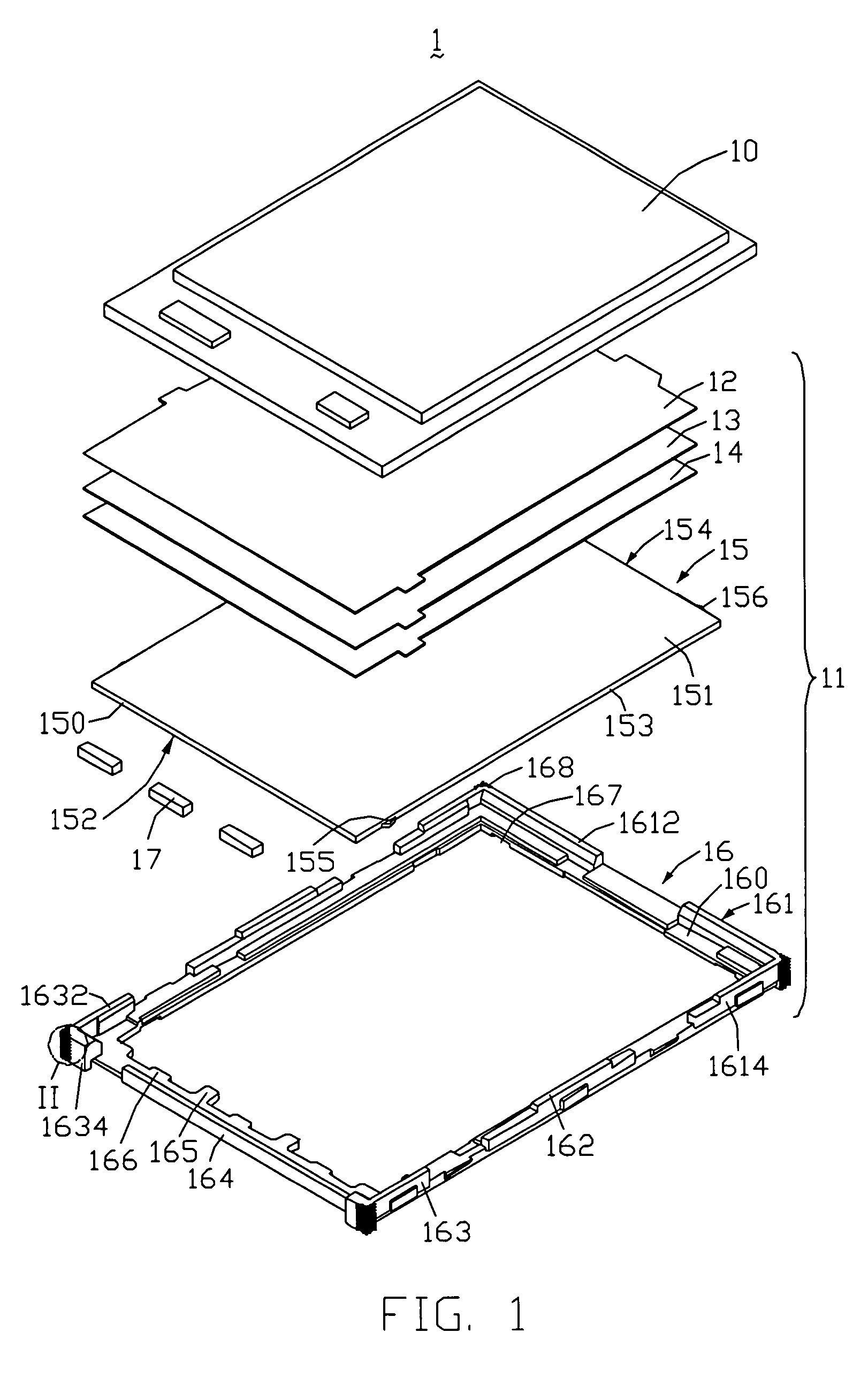
[0016]Referring to FIG. 1, a liquid crystal display 1 according to, the present invention is shown. The liquid crystal display 1 includes a liquid crystal panel 10, and a backlight module 11 adjacent to an underside of the liquid crystal panel 10.

[0017]The backlight module 11 includes a first BEF 12, a second BEF 13, a diffusing film 14, a light guide plate 15, a frame 16, and a bottom tray (not shown) arranged generally in that order from top to bottom. The backlight module 11 further includes three light emitting diodes (LEDs) 17 serving as light sources. The LEDs 17 are located adjacent to a light incident surface 150 of the light guide plate 15.

[0018]The light guide plate 15 further includes a light emitting surface 151 perpendicularly connected with the light incident surface 150, a bottom surface 152 opposite to the light emitting surface 151, two opposite first side surfaces 153 perpendicularly connected with the light incident surface 150, and a second side surface 154 oppos...

second embodiment

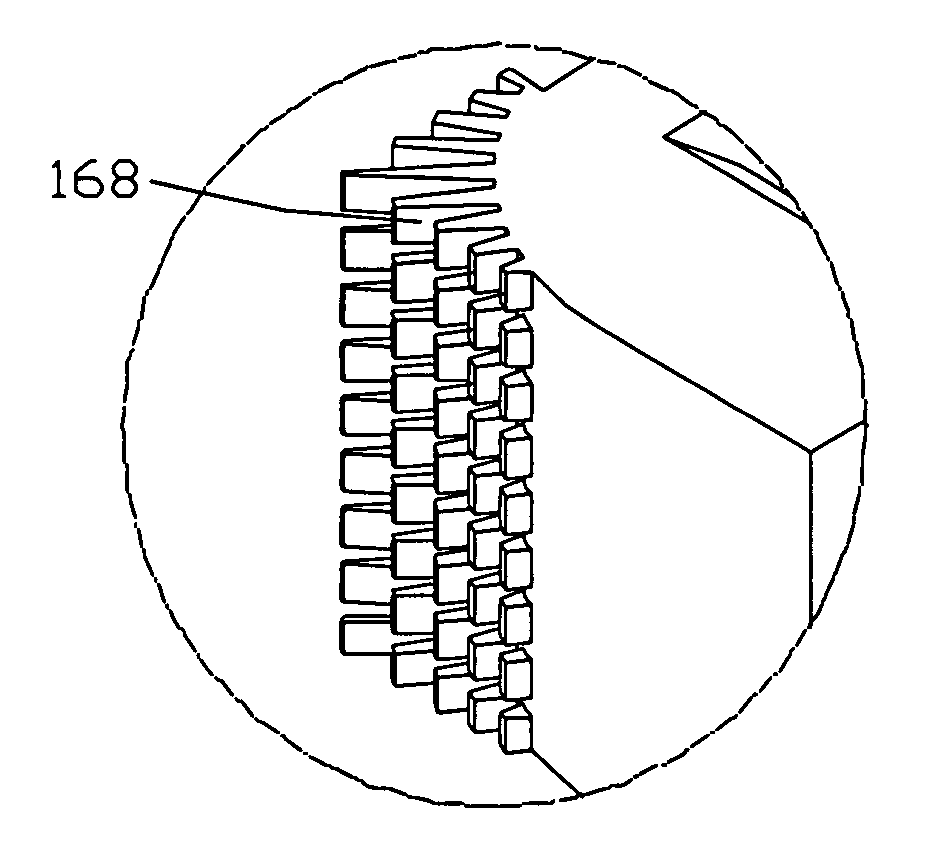
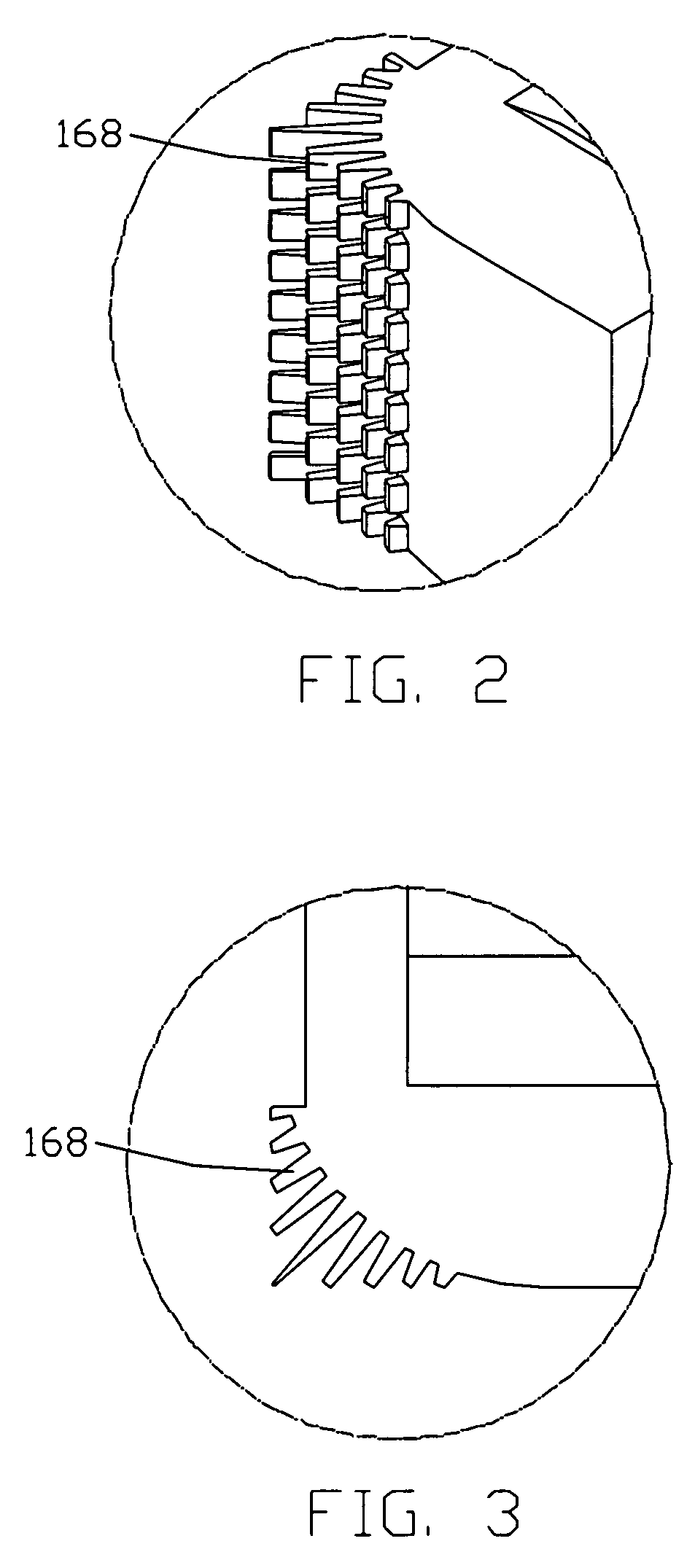
[0030]Referring to FIG. 4, a liquid crystal display 2 according to the present invention is similar to the liquid crystal display 1. However, the liquid crystal display 2 includes a frame 26. The frame 26 includes a plurality of buffering protrusions 268 that outwardly extend from outer sides of two diagonally opposite corners (not labeled) thereof. The liquid crystal display 2 has advantages similar to those described above in relation to the liquid crystal display 1.

[0031]Further or alternative embodiments may include the following. In a first example, the liquid crystal display 1, 2 includes the buffering protrusions 168, 268 at only one of the corners of the frame 16, 26. In a second example, the liquid crystal display 1, 2 includes the buffering protrusions 168, 268 at three of the corners of the frame 16, 26. In a third example, the buffering protrusions 168, 268 have random lengths. In a fourth example, each of the buffering protrusions 168, 268 has one of the following trans...


PUM


Abstract

An exemplary backlight module (11) includes a light guide plate (15) and a frame (16) receiving the light guide plate. The frame includes a plurality, of corners and a plurality of buffering protrusion (168). At least one of the corners is a non-sharp corner, and the buffering protrusions (168) are provided at an outer side of at least one non-sharp corner. The buffering protrusions can absorb most of forces applied to the frame. A liquid crystal display (1) employing the backlight module is also provided.

Description

FIELD OF THE INVENTION[0001]The present invention relates to a backlight module that includes a plurality of buffering protrusions, and to a liquid crystal display (LCD) that includes the backlight module.GENERAL BACKGROUND[0002]Liquid crystal displays are commonly used as display devices for compact electronic apparatuses, because they not only provide good quality images but are also very thin. Because liquid crystal in a liquid crystal display does not emit any light itself, the liquid crystal requires a light source to clearly and sharply display text and images. Therefore, liquid crystal displays typically need a backlight module.[0003]Referring to FIG. 5, a typical liquid crystal display 5 includes a liquid crystal panel 50, and a backlight module 51 located adjacent to the liquid crystal panel 50. The backlight module 51 includes a first brightness enhancement film (BEF) 52, a second BEF 53, a diffusing film 54, a light guide plate (LGP) 55, a plastic frame 56, and a bottom t...

Claims


Application Information

Patent Timeline
Patent Type & Authority Patents(United States)
IPC IPC(8): F21V7/04
CPCG02F1/1339G02F2201/121G02F1/1345
Inventor KUO, CHAO-TSUN
Owner INNOLUX CORP
Features
  • R&D
  • Intellectual Property
  • Life Sciences
  • Materials
  • Tech Scout
  • Unparalleled Data Quality
  • Higher Quality Content
  • 60% Fewer Hallucinations
Learn More