

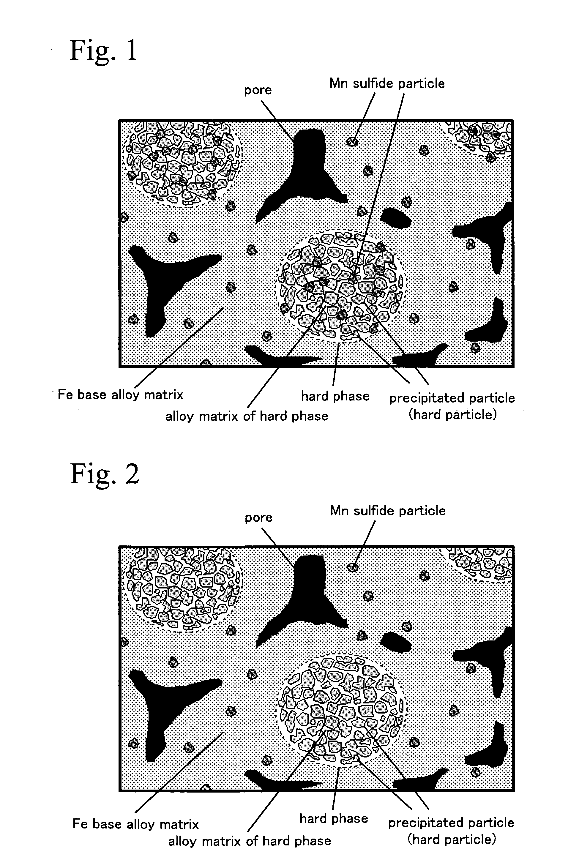
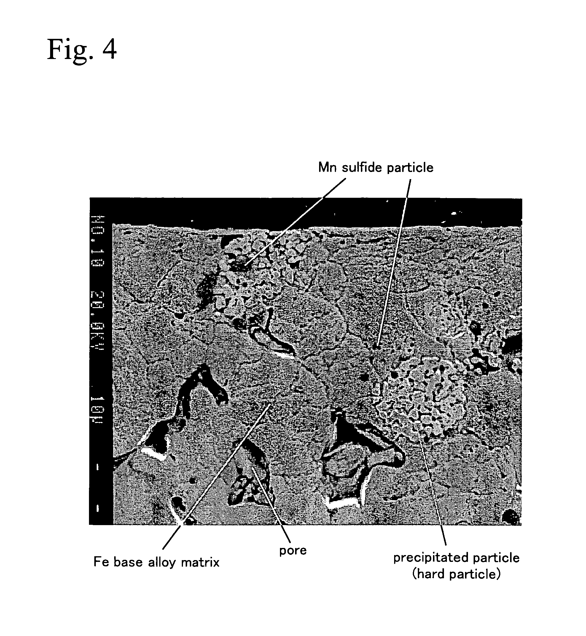
Wear resistant sintered member
a technology of wear-resistant sintered parts and wear-resistant parts, which is applied in the direction of metal-working apparatuses, transportation and packaging, etc., can solve the problems of low machinability of wear-resistant sintered parts such as above, difficult to machine, and need to be improved more, so as to improve the machinability of wear-resistant sintered parts and improve the machinability of wear-resistant sintered members. the effect of more greatly
- Summary
- Abstract
- Description
- Claims
- Application Information
AI Technical Summary
Benefits of technology
Problems solved by technology
Method used
Image

Examples
embodiments
Embodiment 1
[0048]Matrix forming steel powders having compositions shown in Table 1 were prepared. A hard phase forming alloy powder having a composition consisting of 35% of Mo, 3% of Si, 2% of Mn, all by mass %, the balance of Fe and inevitable impurities, and a molybdenum disulfide powder having the maximum particle size of 100 μm and an average particle size of 50 μm, and a graphite powder were prepared. These powders were mixed at rates shown in Table 1 together with a forming lubricant (0.8 mass % of zinc stearate), and the mixed powder was formed into ring-shaped green compacts with an outer diameter of 30 mm, an inner diameter of 20 mm, and a height of 10 mm at a forming pressure of 650 MPa. Then, the green compacts were sintered at 1160° C. for 60 minutes in an decomposed ammonia gas atmosphere, and samples 01 to 06 having compositions shown in Table 2 were produced.
[0049]The metal structure of the samples was observed and the rate of area occupied by precipitated manganese...
embodiment 2
[0062]The matrix forming steel powder (Mn content: 0.5 mass %) used in sample 03 in Embodiment 1, 5 mass % of a hard phase forming alloy powder of which composition is shown in Table 4, 1.0 mass % of a graphite powder, and 1.0 mass % of a molybdenum disulfide powder having the maximum particle size of 100 μm and an average particle size of 50 μm were mixed together with a forming lubricant (0.8 mass % of zinc stearate). The mixed powder was processed with the same conditions as the embodiment 1, and samples 07 to 11 of which compositions are shown in Table 5 were produced. These samples were evaluated with the same conditions as the embodiment 1. The results of the evaluation are shown in Table 6. It should be noted that data of sample 03 in the embodiment 1 is shown together in Tables. 4 to 6.
[0063]
TABLE 4Mixing Ratio (mass %)Hard Phase FormingAlloy PowderMatrix FormingComposition of PowderSulfideSampleSteel Powder(mass %)GraphitePowderNo.(Fe—1.6Ni—1Mo—0.2Cr—0.5Mn)FeMoSiMnPowderTyp...
embodiment 3
[0071]The matrix forming steel powder and the hard phase forming alloy powder used in sample 03 in Embodiment 1, 1.0 mass % of a graphite powder, and a molybdenum disulfide powder having the maximum particle size of 100 μm and an average particle size of 50 μm at amount shown in Table 7 were mixed together with a forming lubricant (0.8 mass % of zinc stearate). The mixed powder was processed with the same conditions as Embodiment 1, and samples 12 to 16 of which overall compositions are shown in Table 8 were produced. These samples were evaluated with the same conditions as Embodiment 1. The results of the evaluation are shown in Table 9. It should be noted that data of sample 03 in Embodiment 1 is shown together in Tables 7 to 9.
[0072]
TABLE 7Mixing Ratio (mass %)Matrix FormingHard Phase FormingSulfideSampleSteel PowderAlloy PowderGraphitePowderNo.(Fe—1.6Ni—1Mo—0.2Cr—0.5Mn)(Fe—35Mo—3Si—2Mn)PowderType12Balance5.001.00MoS20.1013Balance5.001.00MoS20.5003Balance5.001.00MoS21.0014Balance...
PUM
| Property | Measurement | Unit |
|---|---|---|
| particle size | aaaaa | aaaaa |
| mass % | aaaaa | aaaaa |
| mass % | aaaaa | aaaaa |
Abstract
Description
Claims
Application Information