Viscous oil inflow control device for equalizing screen flow

a technology of control device and viscous oil, which is applied in the direction of drinking water installation, borehole/well accessories, construction, etc., can solve the problems of expensive machining and increase the cost of each stand of screen

Inactive Publication Date: 2009-08-25
BAKER HUGHES INC
View PDF28 Cites 70 Cited by
  • Summary
  • Abstract
  • Description
  • Claims
  • Application Information

AI Technical Summary

Problems solved by technology

Using this design would require expensive machining raising the cost of each stand of screen.

Method used


Image

  • Viscous oil inflow control device for equalizing screen flow
  • Viscous oil inflow control device for equalizing screen flow

Examples


Embodiment Construction

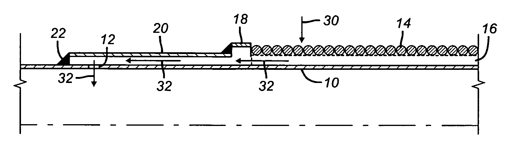
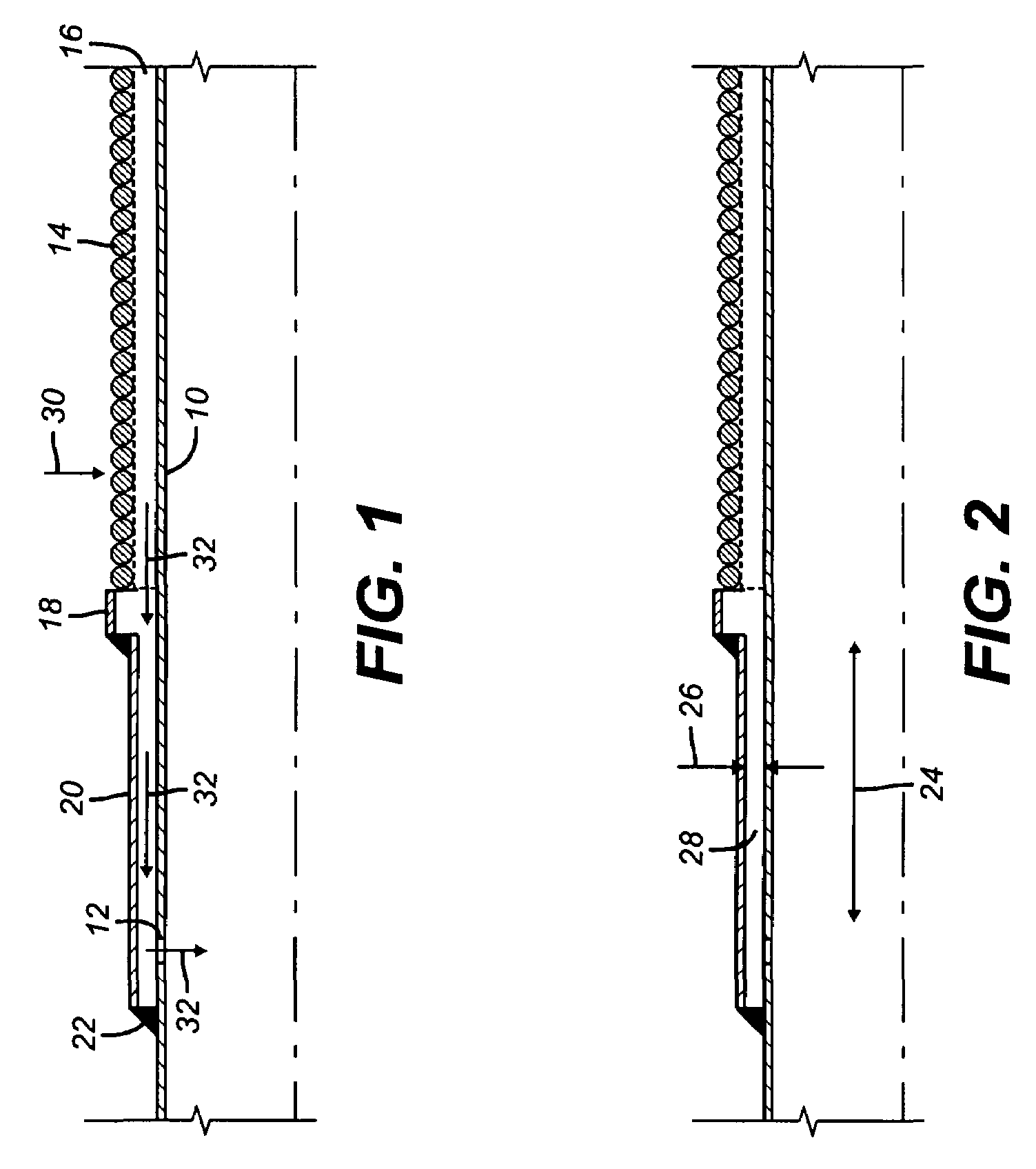
[0008]Referring now to FIG. 1 a base pipe 10 has at least one port 12. A screen 14, such as a wire wrap type for example, goes over the base pipe 10 to define an annular space 16. An end ring 18 is secured in a sealed manner to an end of screen 14 and a sleeve 20 is either integral or extends from end ring 18. Sleeve 20 terminates in a sealed manner against the base pipe 10 at end 22. Those skilled in the art will appreciate that only one end of one screen section is shown to illustrate the manner in which flow is balanced among screen sections in a producing formation. At the other end of the screen section shown in FIG. 1, the opposite end of screen 14 is secured in a sealed manner to the base pipe 10 to define the end of annular space 16. In the preferred embodiment the openings 12 are at the end shown in FIG. 1 but the screen section in FIG. 1 can have a mirror image at the opposite and end not shown as the end illustrated in FIG. 1. If that is done the length 24 of passage 28 a...


PUM


Abstract

A flow balancing system for long screen sections particularly useful in high viscosity hydrocarbon production features an annular flow path whose height and length can be varied to provide a predetermined resistance to a given flow rate of a material of a given viscosity. In assembling a long length of screen sections, greater resistance configurations are placed closer to the wellhead end of the screen section with the more remote sections having progressively less restriction until the furthest section of the screen string where low or no resistance to flow internally to the screen section is offered.

Description

FIELD OF THE INVENTION[0001]The field of the invention is production techniques for equalizing flow from formations and more particularly from formations that produce more viscous hydrocarbons in the preferred range of about 20-1000 centipoise.BACKGROUND OF THE INVENTION[0002]Some completions involve long runs of screens in the producing zone. To get more balanced production along a lengthy section of screen that in some cases could be thousands of feet long devices have been used to offer different resistance at different locations along the screen sections. The screen sections closest to the surface that constitute a potential path of least resistance would need more restriction that screen sections further down. What has been tried in the past is illustrated in U.S. Pat. No. 6,622,794. In this patent screen sections had an annular space between a base pipe and the screen and inserted in the annular space before the flow could get to openings in the base pipe were helical paths th...

Claims


Application Information

Patent Timeline
Patent Type & Authority Patents(United States)
IPC IPC(8): E21B43/00
CPCE21B43/08E21B34/08
Inventor AUGUSTINE, JODY R.
Owner BAKER HUGHES INC
Why Eureka
Try Eureka