Method and system for emitter localisation

a technology of emitter localisation and method, applied in direction finders using radio waves, radio wave reradiation/reflection, radio wave reradiation, etc., can solve the problems of insufficient method accuracy, significant increase in computer/processor performance requirements, and insufficient accuracy of methods. , to achieve the effect of limited inter-aircraft transmission rate, limited computation costs, and high accuracy

Inactive Publication Date: 2009-08-25
AIRBUS DEFENCE & SPACE
View PDF36 Cites 37 Cited by
  • Summary
  • Abstract
  • Description
  • Claims
  • Application Information

AI Technical Summary

Benefits of technology

[0004]Processes have therefore been designed in which use is made of direction-finding beams from two airplanes that simultaneously intercept the same emitter. As a result of this, the transient triangulation base can be enlarged significantly so that it becomes possible even to locate emitters that are switched on only briefly.
[0013]An additional object for the invention is that such a process can be implemented with limited computation costs and with a limited inter-aircraft transmission rate in an airplane system even in the case of a that the number of intercepted emitters is greater than two per frequency band of the participating sensors.

Problems solved by technology

This method, however, has an insufficient accuracy in the case of emitters that are switched on briefly (with an emitting period of 15 seconds or less) and that are located at distances between the airplane and the emitter (greater) larger than approximately 25 km.
In the case of many emitters in the covered area, however, this process of multi-platform-triangulation has the disadvantage that the number of geometrical intersection points is significantly higher than the number of real emitter positions.
A disadvantage with the use of this method is that, in the case of the occurrence of a large number of emitters, the number of intersection points increases as a function of n2 with increasing the number n of emitter targets, and thus the requirements that are set for computer / processor performance increase very markedly.
In the case that “emitter bearing lines” are only available transiently, on the other hand, the observation time is too short in many scenarios in order to be able to differentiate virtual intersection points reliably from a true target position.
This method results in a very complex and hence costly process.

Method used


Image

  • Method and system for emitter localisation
  • Method and system for emitter localisation
  • Method and system for emitter localisation

Examples


Embodiment Construction

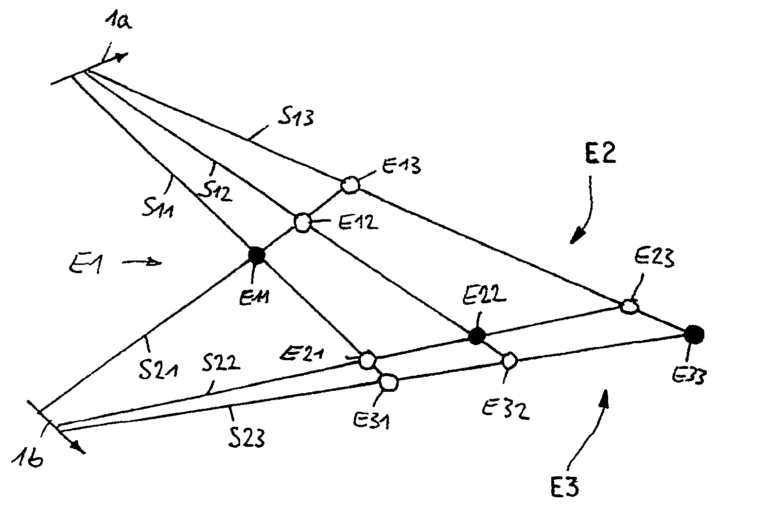
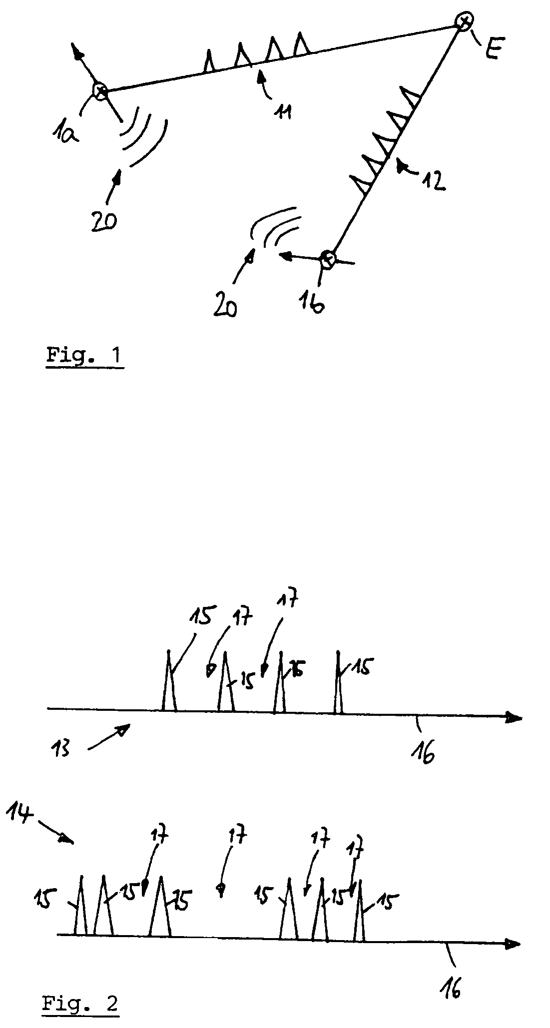
[0025]Employment of the invention is envisaged in a configuration of at least two flying platforms implementing the system or process in accordance with the invention, whereby the flying platforms can be manned or unmanned flying vehicles. Such a constellation is illustrated in FIG. 1 by means of a first flying platform or a first flying device or airplane 1a, and by means of a second flying platform or a second flying device or airplane 1b. Flying platforms 1a, 1b (and optionally additional flying platforms 1c: see FIG. 7) are components of a military operational formation and have the task of detecting and locating enemy emitters, in the radar frequency range, on the basis of cross bearing via passive RF sensors that are integrated into the platforms or flying vehicles. By way of example, such an enemy emitter E is illustrated in FIG. 1.

[0026]Emitter E sends out pulse sequences in the radar frequency range, whereby two pulse sequences 11, 12 are symbolically illustrated in FIG. 1....


PUM


Abstract

Process and system for the location of emitters in the radar frequency range on the basis of cross position-finding by at least two flying platforms with, in each case, at least one passive HF sensor for ascertaining the geometrical and electronic properties of the emitter beams, whereby the flying platforms mutually exchange data for describing the geometrical and electronic properties of the emitter beams, and whereby from the plurality of the position-finding beams' possible intersection points, which arise from the emitter surveying operation, use is made, in order to determine the emitter position, of those intersection points at which the electronic properties of the intersecting emitter beams are identical.

Description

BACKGROUND OF THE SUMMARY OF THE INVENTION[0001]This application claims the priority of German Patent Document No. 101 43 561.4, filed 5 Sep. 2001, and PCT / DE02 / 03238, filed 3 Sep. 2002 the disclosure of which is expressly incorporated by reference herein, respectively.[0002]The invention pertains to a process and a system for the location of emitters in the radar frequency range that is based on cross bearing (multi-platform triangulation) via airborne passive high frequency (RF) sensors.[0003]Today, emitters in the radar frequency range are surveyed and located from a single airplane by means of continuous direction-finding and subsequent triangulation of the direction-finding beams. This method, however, has an insufficient accuracy in the case of emitters that are switched on briefly (with an emitting period of 15 seconds or less) and that are located at distances between the airplane and the emitter (greater) larger than approximately 25 km.[0004]Processes have therefore been d...

Claims


Application Information

Patent Timeline
Patent Type & Authority Patents(United States)
IPC IPC(8): G01S3/02G01S13/08G01S5/04G01S7/02G01S13/00
CPCG01S5/04G01S7/021G01S13/003
Inventor WINTERLING, GERHARDBENNINGHOFEN, BENJAMIN
Owner AIRBUS DEFENCE & SPACE
Why Eureka
Try Eureka