Distance/ranging determination using relative phase data

a technology of distance/ranging and relative phase, applied in the field of radio frequency identification tags, can solve the problems of prior art interrogator not being able to determine whether the rf tag is in front of, behind, or to either side of the interrogator, and cannot determine whether it is 90 meters or 45 meters away

Inactive Publication Date: 2009-08-25
RUIZHANG TECH LTD CO
View PDF19 Cites 100 Cited by
  • Summary
  • Abstract
  • Description
  • Claims
  • Application Information

AI Technical Summary

Problems solved by technology

Although prior art communication systems can communicate with an RF tag that is within a certain distance of the interrogator (depending on the interrogator power), the interrogator cannot determine the location of the RF tag.
For example, the prior art interrogator may be able to determine that there is an RF tag within 100 meters of the interrogator, but cannot determine whether it is 90 meters away or 45 meters away.
In addition, the prior art interrogator cannot determine whether the RF tag is in front of, behind, or to either side of the interrogator.

Method used


Image

  • Distance/ranging determination using relative phase data
  • Distance/ranging determination using relative phase data
  • Distance/ranging determination using relative phase data

Examples


Embodiment Construction

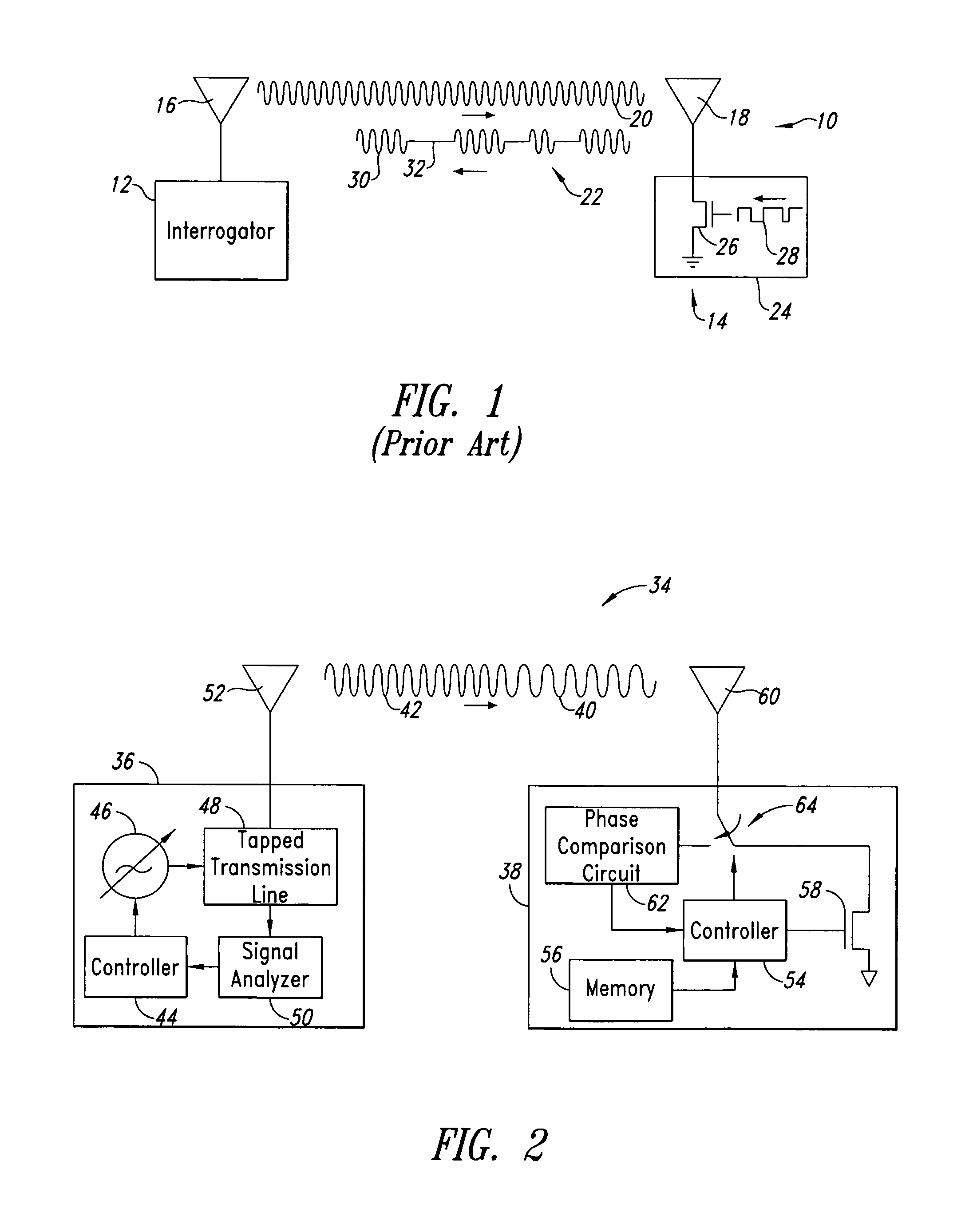
[0031]As shown in FIG. 2, an embodiment of the present invention is directed to an RF communication system 34 that determines a distance between a reader or interrogator 36 and an RF transponder or tag 38. The system 34 determines the distance by transmitting from the interrogator 36 to the RF tag 38 a first signal 40 at a first frequency and a frequency modulated second signal 42 at a second frequency. The RF tag 38 compares the signals 40, 42 and determines a phase difference between the two signals. The distance between the interrogator 36 and the RF tag 38 is directly related to that detected phase difference.

[0032]The interrogator 36 includes a controller 44, a variable signal source 46, a tapped transmission line 48, a signal analyzer 50, and an antenna 52. The controller 44 can be any general purpose processor, such as a known microprocessor, or can be specifically designed to control the operation of the interrogator 36 as described herein. Examples of the tapped transmissio...


PUM


Abstract

A method and system for locating an RF transponder based on phase differences between signals received from the RF transponder. The method includes receiving a signal from the transponder and calculating distance, relative movement, and position by comparing I-Q phase angle vectors of the signals. Global scroll commands can be used following receipt of signals at first and second frequencies to quickly determine distance.

Description

[0001]The present patent application is a Continuation-In-Part (CIP) of application Ser. No. 09 / 588,998, filed Jun. 6, 2000, which is issued as U.S. Pat. 6,868,073 on Mar. 15, 2005.BACKGROUND OF THE INVENTION[0002]1. Field of the Invention[0003]The present invention relates to radio frequency identification tags (RF tags), and in particular, to an RF communication system and method for locating RF tags utilizing relative phase information from multiple channels.[0004]2. Description of the Related Art[0005]Remote communication utilizing wireless equipment typically relies on radio frequency (RF) technology, which is employed in many industries. One application of RF technology is in locating, identifying, and tracking objects, such as animals, inventory, and vehicles.[0006]RF identification (RFID) tag systems have been developed that facilitate monitoring of remote objects. As shown in FIG. 1, a basic RFID system 10 includes two components: an interrogator or reader 12, and a transpo...

Claims


Application Information

Patent Timeline
Patent Type & Authority Patents(United States)
IPC IPC(8): H04B7/005G01S13/82G01S5/14G01S13/84G01S19/14G01S19/34
CPCG01S13/84G01S5/14
Inventor CARRENDER, CURTIS LEEPRICE, JOHN M.
Owner RUIZHANG TECH LTD CO
Why Eureka
Try Eureka