Work support

a technology for supporting devices and supports, applied in the field of work supports, can solve the problems of lack of flexibility in the provision of dedicated support arrangements

Active Publication Date: 2009-09-01
ROLLS ROYCE PLC
View PDF13 Cites 16 Cited by
  • Summary
  • Abstract
  • Description
  • Claims
  • Application Information

AI Technical Summary

Problems solved by technology

Clearly, provision of such dedicated support arrangements lacks flexibility in terms of change over times to enable different components to be machined and so at least is inconvenient.

Method used


Image

  • Work support
  • Work support
  • Work support

Examples


Embodiment Construction

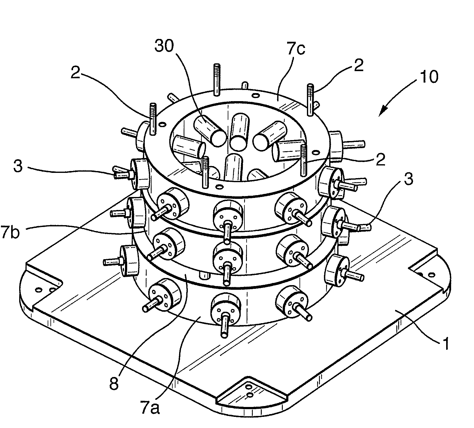
[0015]As indicated above, a support arrangement capable of accommodating a range of components with similar geometry but different sizes would be advantageous. An ability to adapt a modular support arrangement so that it can be re-configured quickly to support components with different heights and diameters would be beneficial. Clearly, support ends to engage a component or article to be machined or supported may be displaceable into engagement but nevertheless positioning of the support ends at different heights and diameters will be necessary.

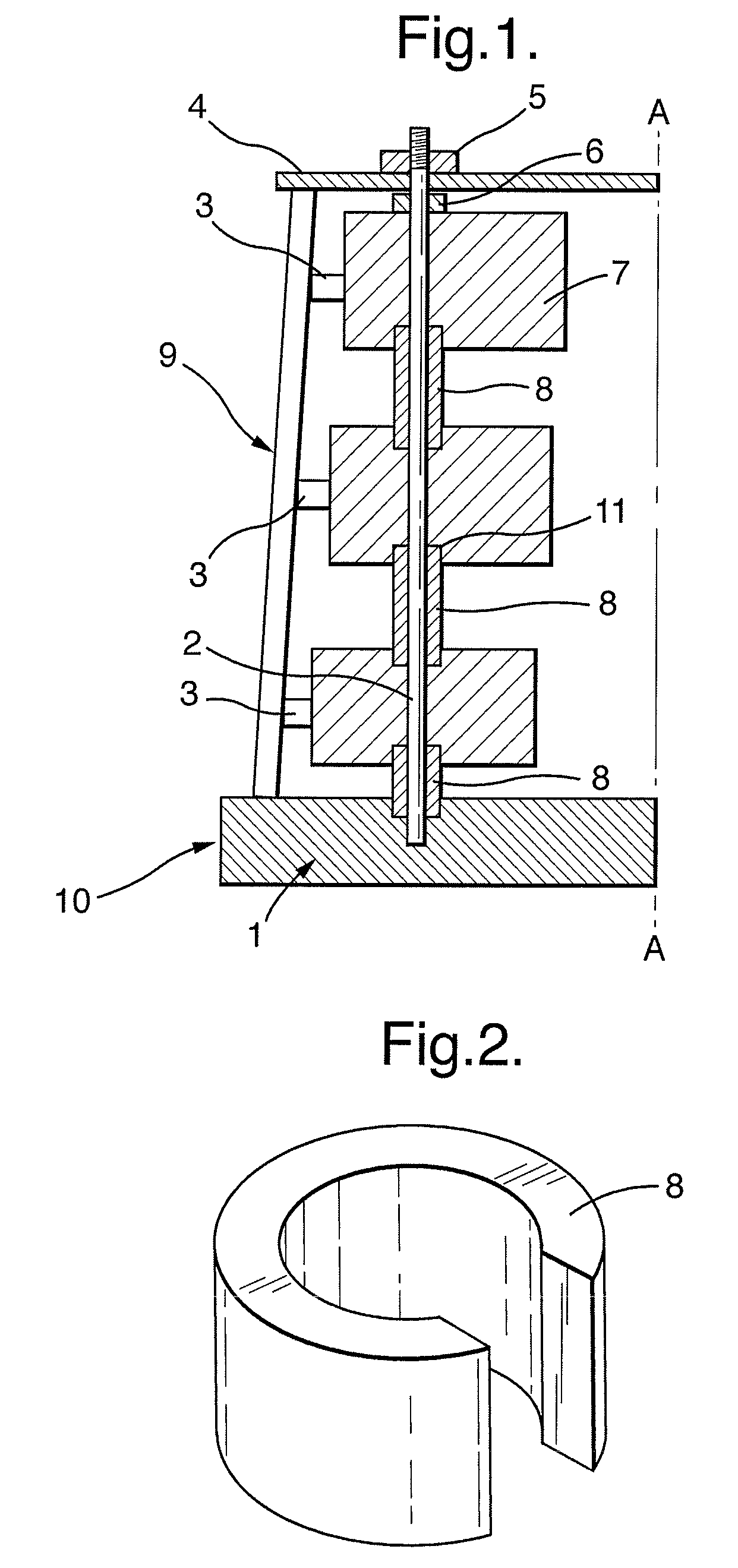
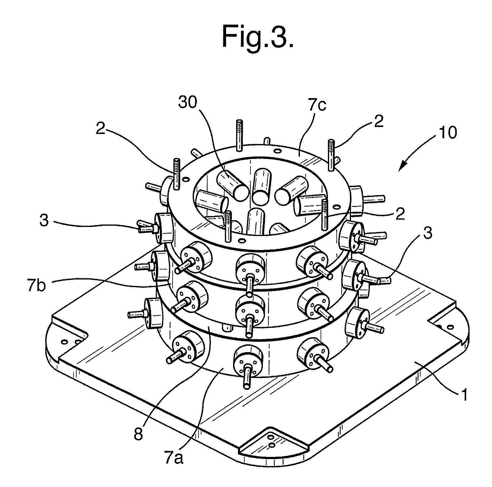
[0016]FIG. 1 illustrates schematically as a side cross section a work support arrangement 10 in accordance with aspects of the present invention. The arrangement 10 comprises a base 1 upon which a mounting structure is created through an upright post 2 with rings 7 secured upon the posts 2. Each ring 7 incorporates at least one work support 3, which in turn is arranged to engage an article 9 such as a component having a thin walled surface. F...


PUM


Abstract

It is necessary to support components while machining is performed. In such circumstances work supports are now provided, whilst previously there was a dedicated arrangement for each component to be supported. By achieving a modularity in terms of adjustment through creating mountings comprising rings, arcs or bars secured upon posts a rigidity of presentation of support ends is achieved. By providing spacers for location about the posts on the mountings variability with regard to the positioning of the support ends is achieved such that similar geometry but different sized components and articles can be supported by the support arrangements. Furthermore, the spacers may be readily removed if C shaped, and the rings, arcs or bars can be shifted.

Description

CROSS-REFERENCE TO RELATED APPLICATION[0001]This application is entitled to the benefit of British Patent Application No. GB 0702087.8 filed on Feb. 3, 2007.FIELD OF THE INVENTION[0002]The present invention relates to work supports generally and more particularly to work supports used to support thin walled components such as casings whilst these components are machined.BACKGROUND OF THE INVENTION[0003]It will be appreciated that some components are generally cast or otherwise formed ready for final machining through such processes as milling and drilling. To facilitate such machining processes a support structure is required and so work support arrangements are designed for particular components. It will be appreciated in view of the nature of some components which may be thin walled it is typically necessary to avoid distortion and damage as a result of the machining forces. Thus, it is not unusual to provide dedicated support arrangements and fixtures for each component. Clearly,...

Claims


Application Information

Patent Timeline
Patent Type & Authority Patents(United States)
IPC IPC(8): B23Q3/00
CPCB23Q1/035B23Q3/103B23Q3/062B23Q2240/005B23Q3/06B23Q3/10B23Q3/105B25B5/006
Inventor GARRY, IAN MURRAYWANG, YANXIE, JIANFANGINDY, NABIL
Owner ROLLS ROYCE PLC
Why Eureka
Try Eureka