Air bag device

a technology of airbags and axial ends, which is applied in the direction of vehicular safety arrangements, pedestrian/occupant safety arrangements, vehicle components, etc., can solve the problems of affecting the safety of passengers, the position of the inflating bag in the approaching/separating direction of the window cannot be controlled, and the risk of one axial end of the inflating bag tilting in an upward direction, etc., to achieve the effect of easy formation

Inactive Publication Date: 2009-09-01
HONDA MOTOR CO LTD +1
View PDF23 Cites 18 Cited by
  • Summary
  • Abstract
  • Description
  • Claims
  • Application Information

AI Technical Summary

Benefits of technology

[0015]Since the impact absorption member is thus interposed between the air bag and the lining, when an occupant slams into the lining, the impact can be absorbed by both the lower portion of the air bag and the impact absorption member. Accordingly, greater impact absorption is made possible.
[0027]According to this constitution, since the coupling member straddles the top of the air bag to be passed over the cabin interior side portion and the cabin exterior side portion thereof during deployment of the air bag, the air bag including the coupling member can be easily formed.

Problems solved by technology

At this time, centered on a coupling portion between the air bag and the housing portion, there is a risk of one axial end of the inflating bag tilting in an upward direction.
However, when the air bag deploys, its position in the approaching / separating direction with respect to the window cannot be controlled.
However, when using a roof side air bag and a door-mounted air bag device (that is, an air bag device that deploys an air bag upwardly from below a window) in combination, problems arise.
That is, providing the tension line for the roof side air bag leads to structural difficulties that cause the deployment direction of the air bag to become unstable.

Method used


Image

  • Air bag device
  • Air bag device
  • Air bag device

Examples


first embodiment

[0046]The first embodiment of the air bag device according to the present invention shall be explained first, referring to FIGS. 1 to 3.

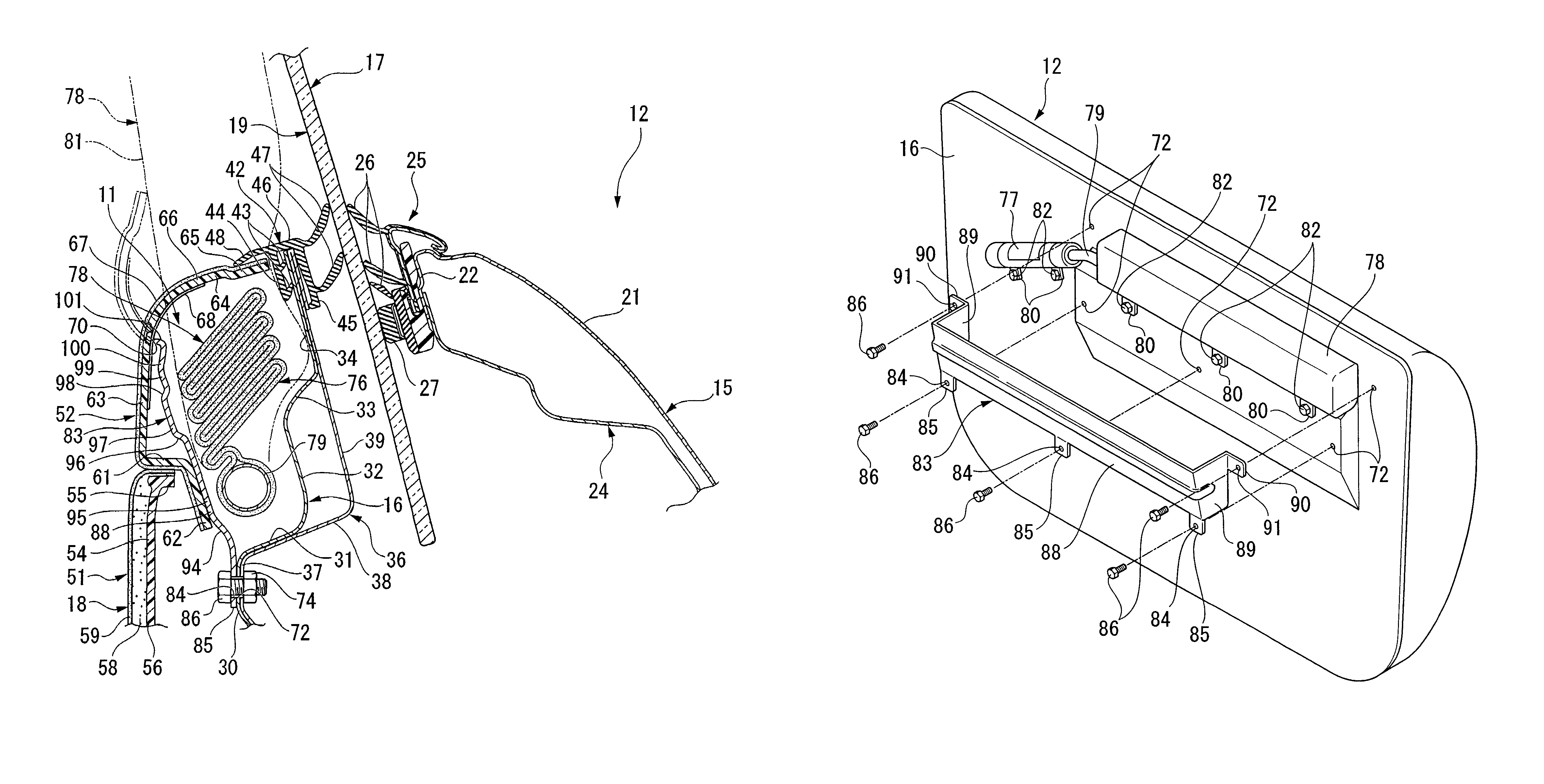
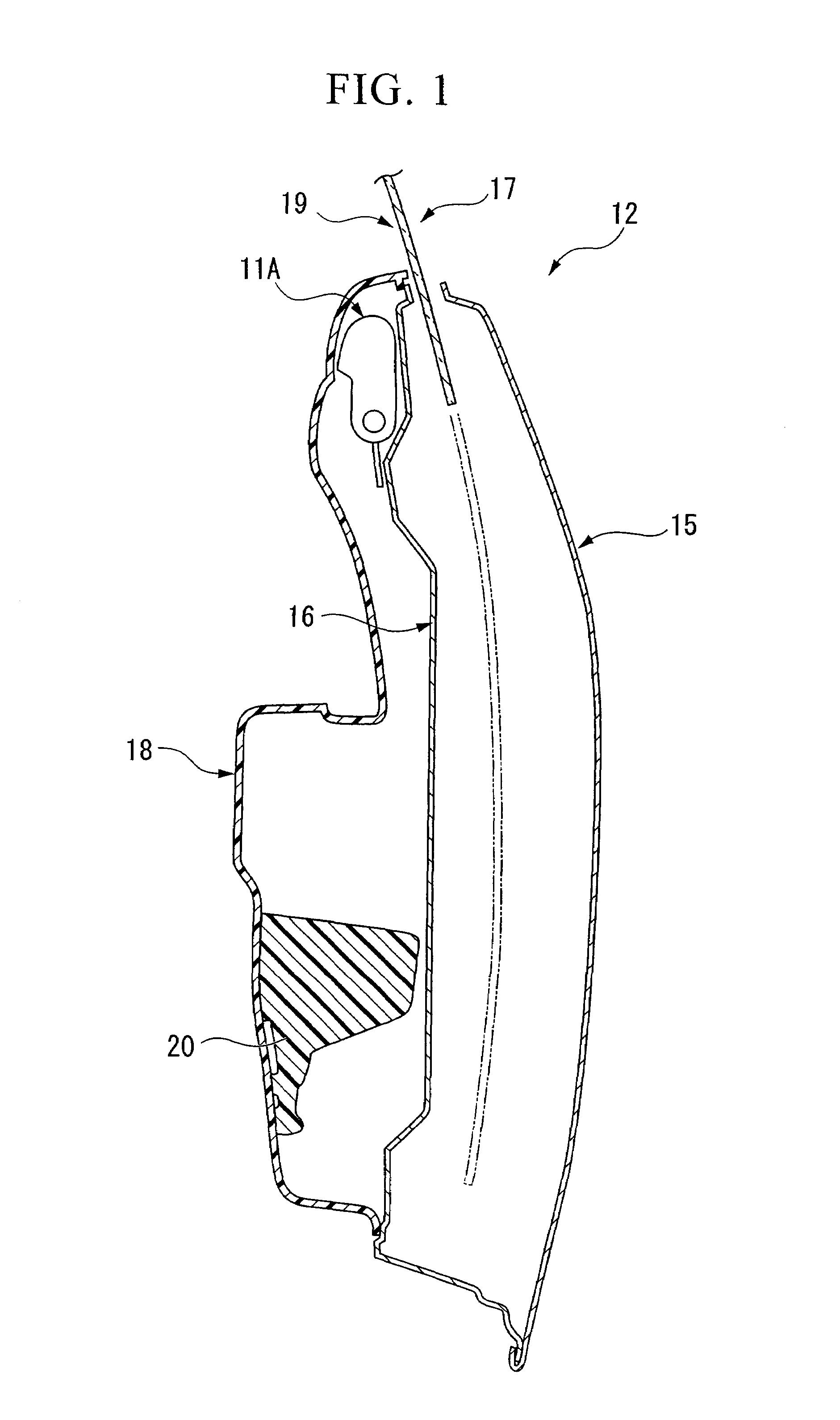
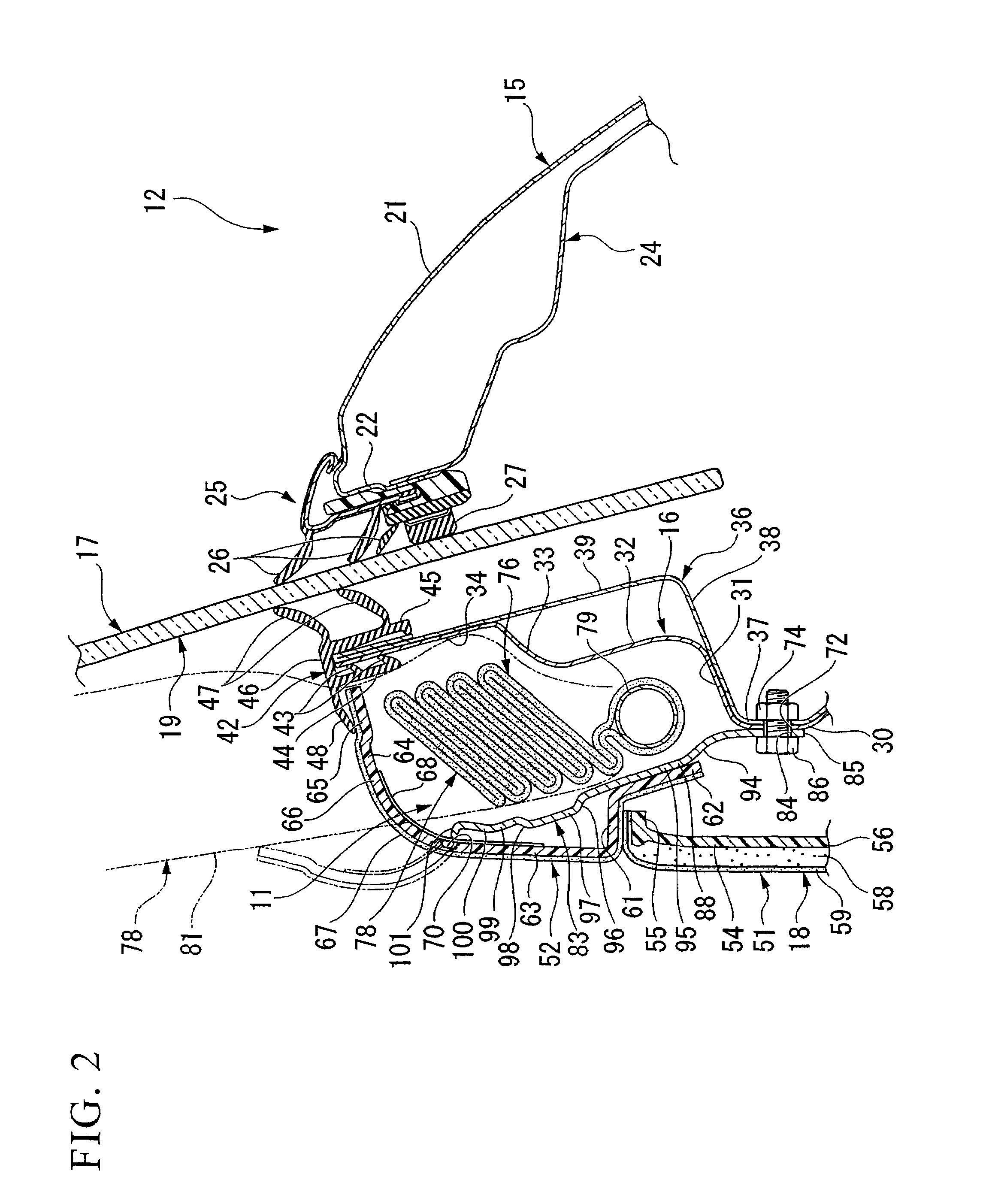
[0047]FIG. 1 schematically shows the cross section of a door 12 on the right side of a vehicle in which an air bag device 11A according to the present embodiment is provided. In the drawing, the left side of the sheet is a cabin interior side, and the right side of the sheet is a cabin exterior side. Here, the vehicle to which the air bag device 11A is provided is an open-roof vehicle in which the roof can be opened and closed or is detachable. Note that in the explanation given below, the door 12 is in a closed state.

[0048]The door 12 includes an outer panel 15 made of metal, an inner panel (panel) 16 made of metal, a window glass 17 that can move up and down, and a door lining (lining) 18. The outer panel 15 is disposed along a vehicle longitudinal direction on the cabin exterior side, and composes the design surface of the cabin exterior side. Th...

second embodiment

[0069]Next, the air bag device according to the second embodiment of the present invention shall be explained, referring to FIGS. 4 to 10. The explanation shall focus on components differing from the aforementioned first embodiment. Therefore, components similar to those in the first embodiment shall be given the same reference numerals and explanations thereof shall be omitted here.

[0070]An air bag module of an air bag device 11B of the present embodiment includes the inflator 77, and the pipe 79 shown in FIG. 2 or FIG. 3, and additionally an air bag 178A shown in FIG. 4. This air bag module is, as shown in FIG. 4, disposed in a housing portion 182 that forms along the lower border of the window 19. The housing portion 182 is formed by the upper portion of the inner panel 16 (shown in cross section in FIG. 2) and the upper portion of the door lining 18 (shown in cross section in FIG. 2). Also, the impact absorption member 83 (shown in cross section in FIG. 2) is provided similarly ...

third embodiment

[0083]Next, the air bag device according to the third embodiment of the present invention shall be explained, referring to FIGS. 11 to 14. The explanation shall focus on components differing from the aforementioned first embodiment. Therefore, components similar to those in the first embodiment shall be given the same reference numerals and explanations thereof shall be omitted here.

[0084]An air bag module of an air bag device 11C of the present embodiment includes the inflator 77, and the pipe 79 shown in FIG. 2 or FIG. 3, and additionally an air bag 278A shown in FIG. 11. This air bag module is, as shown in FIG. 11, disposed in a housing portion 182 that forms along the lower border of the window 19. Also, the impact absorption member 83 (shown in cross section in FIG. 2) is provided similarly to the aforementioned first embodiment, but its illustration is omitted in the present embodiment.

[0085]The air bag 278A is, in a contracted state, folded so as to be successively piled upwa...


PUM


Abstract

An air bag device comprising an air bag that is disposed between an under-window panel and a lining that covers a cabin interior side thereof and deploys upward along an inside surface of the window; and an impact absorption member that interposes between the air bag and the lining.

Description

BACKGROUND OF THE INVENTION[0001]1. Field of the Invention[0002]The present invention relates to an air bag device that deploys an air bag upward along a window from below the window.[0003]Priority is claimed on Japanese Patent Application No. 2005-227662, filed Aug. 5, 2005, Japanese Patent Application No. 2005-227663, filed Aug. 5, 2005, and Japanese Patent Application No. 2005-227664, filed Aug. 5, 2005, the content of which is incorporated herein by reference.[0004]2. Description of Related Art[0005]Among air bag devices used as occupant protective devices mounted in a vehicle, there is known a door-mounted air bag device. As such an air bag device, there is known for example the air bag device disclosed in Japanese Patent No. 2941879, in which an air bag disposed between an inner panel of a door and a lining that covers the cabin interior side thereof is deployed upward along the inside surface of the window.[0006]As shown in FIG. 17, in a typical structure of a vehicle door, m...

Claims


Application Information

Patent Timeline
Patent Type & Authority Patents(United States)
IPC IPC(8): B60R21/20B60R21/21B60R21/231
CPCB60R21/21B60R21/23138B60R21/233
Inventor OCHIAI, FUMIHARUYASUHARA, FUMITOSHINISHIDA, YUSUKEKOBAYASHI, SATOSHIHIGANO, MAKOTO
Owner HONDA MOTOR CO LTD
Why Eureka
Try Eureka