
High-strength high-toughness submerged arc welding wires

A submerged arc welding wire, high toughness technology, applied in arc welding equipment, welding medium, welding equipment and other directions, can solve the problem of lack of accuracy, difficult to use marine engineering equipment, etc., to achieve the effect of stable welding wire quality

Inactive Publication Date: 2013-09-04
TIANJIN UNIV +1
View PDF14 Cites 15 Cited by
  • Summary
  • Abstract
  • Description
  • Claims
  • Application Information

AI Technical Summary

Problems solved by technology

[0004] In the past, there have been many studies on submerged arc welding wires suitable for pipeline steel, construction steel, bridge steel and pressure vessel steel, including the H06C series submerged arc welding wire for new micro-alloyed structural steel with patent publication number CN1701904A, patent publication number It is CN101342645A high-strength high-toughness high-speed submerged arc welding wire for high-grade pipeline steel, patent publication number CN1200317A low-alloy high-strength high-toughness submerged arc welding wire, patent publication number CN1919524A low-alloy ultra-high-strength steel high-toughness submerged arc welding wire Arc welding wire and the patent publication number are CN1343544A high-strength and high-toughness submerged arc welding wire for pressure vessel welding, etc., and their alloy systems basically belong to Si-Mn-Mo-Ti-B and Si-Mn-Ni-Mo systems. The Ni content in the welding wire is low, generally less than 1.5%. Although the toughness can be improved to a certain extent through Ti-B microalloying, the low-temperature impact toughness of the weld metal can only meet the requirements of -40°C. There is no exact data on the fracture toughness index required for welding of marine engineering equipment, and it is difficult to apply it to marine engineering equipment

Method used


Image

  • High-strength high-toughness submerged arc welding wires

Examples


Embodiment Construction

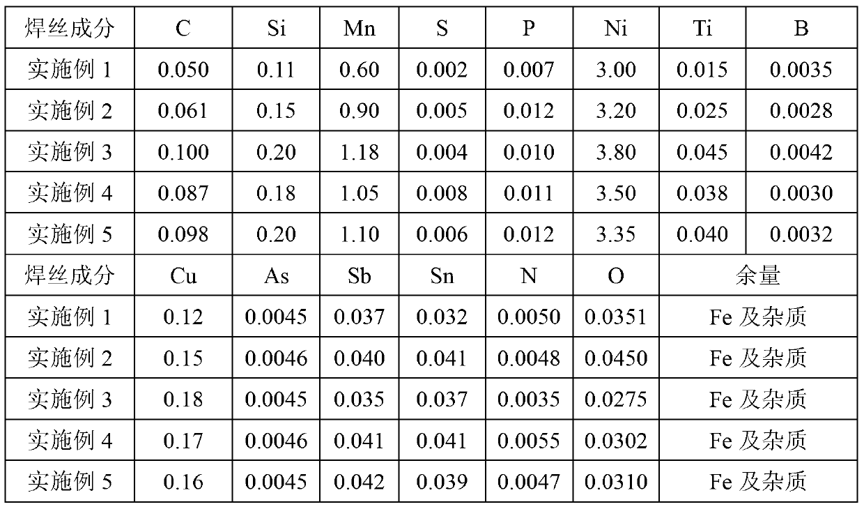
[0018] The present invention is a high-strength and high-toughness submerged arc welding wire. Its chemical composition is calculated by weight percentage: C0.050~0.100, Si≤0.20, Mn0.6~1.20, Ni3.00~3.80, Ti0.01~0.05, B0.001~0.005, Cu≤0.20, S≤0.008, P≤0.010, As≤0.005, Sb≤0.005, Sn≤0.005, N≤0.006, O≤0.005, the balance is Fe and inevitable impurities.

[0019] The present invention will be further described in detail below in conjunction with specific embodiments. The embodiments are provided for the convenience of understanding and are by no means limiting the present invention.

[0020] Table 1 Example submerged arc welding wire composition (wt%)

[0021]

[0022] The welding wire of the present invention is matched with the SJ102 flux to weld the deposited metal test plate, the test plate is FH40, the thickness is 20mm, the groove angle is 10°, and the root gap is 16mm. Welding specifications are: welding current 470~570A, welding voltage 27~34V, welding speed 400~450mm / min, interla...


PUM

PropertyMeasurementUnit
yield strengthaaaaaaaaaa
impact absorption energyaaaaaaaaaa

Abstract

The invention discloses high-strength high-toughness submerged arc welding wires. Chemical components of the wires comprise, by weight, 0.05-0.10% of C, no more than 0.20% of Si, 0.6-1.20% of Mn, 3.00-3.8% of Ni, 0.01-0.05% of Ti, 0.001-0.005% of B, no more than 0.02% of Cu, no more than 0.008% of S, no more than 0.010% of P, no more than 0.005% of As, no more than 0,005% of Sb, no more than 0.005% of Sn, no more than 0.006% of N, no more than 0.05% of O and the balance Fe and unavoidable impurities. A manufacturing method sequentially comprises the steps of molten iron desulphurization, converter iron smelting, LF furnace refining, continuous casting, wire rolling, coil rod shelling, acid picking, borax coating, wire drawing and copper plating, and then the finished welding wires with the diameters being respectively 3.2mm and 4.0mm are manufactured. Fracture toughness delta0 (-10 DEG C) is more than or equal to 0.25mm, the welding wires are applicable to 420-460 MPa level low-alloy high-strength steel, and the welding wires can be used in welding of the important structures like ocean engineering structures, bridges, ships and pressure vessels.

Description

Technical field [0001] The invention relates to the field of welding materials, in particular to a high-strength and high-toughness submerged arc welding wire. Background technique [0002] With the rapid growth of global demand for oil and gas energy, it is becoming increasingly difficult to extract land resources, and the vast ocean has become a new growth point for oil and gas resource extraction. Correspondingly, the marine equipment manufacturing industry has also become a key industry that countries all over the world are developing. Offshore equipment is a typical high-tech, high-value-added product with the characteristics of a long industrial chain, strong driving force, and huge development potential. In the manufacturing of offshore equipment, the largest use is high-strength steel with a yield strength of 350-420MPa. Because the offshore structure has the characteristics of high strength, large plate thickness, and stress concentration due to the interaction of curve...

Claims


Application Information

Patent Timeline
Patent Type & Authority Applications(China)
IPC IPC(8): B23K35/24B23K9/18
Inventor 张智孟宪群黄世明冯灵芝
Owner TIANJIN UNIV
Learn More