Damping device

A technology of anti-vibration device and shock absorber, which is applied in the directions of transportation and packaging, vibration suppression adjustment, non-rotational vibration suppression, etc. It can solve the problems of not fully improving the comfort of the operator, and achieve the suppression of front and rear bumps or sideways movement , Improve riding comfort, excellent elastic properties

Inactive Publication Date: 2010-02-03
KOMATSU LTD
View PDF2 Cites 15 Cited by
  • Summary
  • Abstract
  • Description
  • Claims
  • Application Information

AI Technical Summary

Problems solved by technology

However, in the technologies described in the above-mentioned Patent Documents 1 and 2 or other existing technologies, sufficient consideration has not been given to impacts applied from the left and right directions behind the vehicle frame, and there is a problem that the operator's ride comfort cannot be sufficiently improved.

Method used


Image

  • Damping device
  • Damping device
  • Damping device

Examples


no. 1 approach

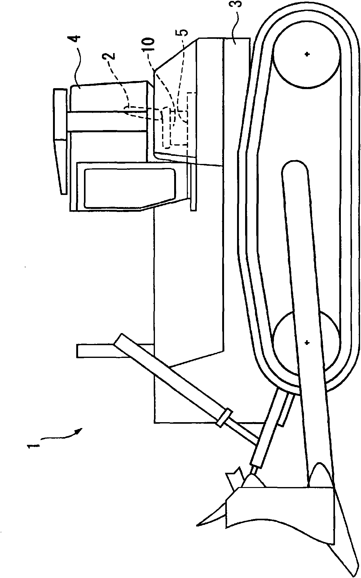
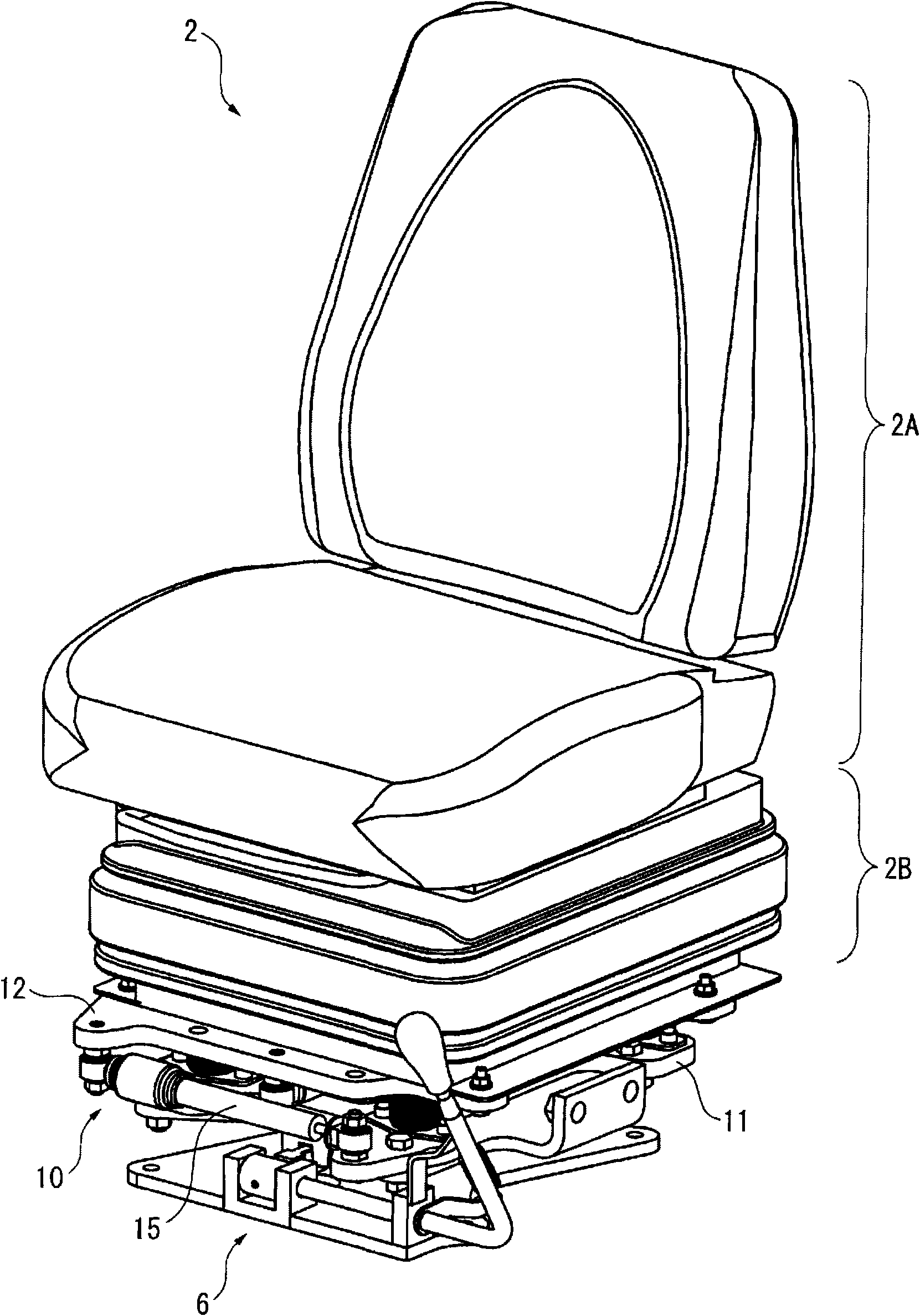
[0032] figure 1 It is a side view schematically showing a bulldozer 1 as a construction machine to which the anti-vibration device 10 of the present embodiment is applied, figure 2 It is a perspective view showing the seat portion to which the anti-vibration device 10 is attached. The anti-vibration device 10 is installed under the seat body 2 of the bulldozer 1 . Specifically, a cab 4 is provided on the vehicle frame 3 of the bulldozer 1 , and in the cab 4 , the anti-vibration device 10 is installed between the floor 5 and the seat body 2 .

[0033] To be more specific, as figure 2 As shown, in the anti-vibration device 10 and the bottom plate 5 ( figure 1 ) is provided with a seat rotation mechanism 6, through handle operation, the seat body 2 and the anti-vibration device 10 can be rotated together within a specified angle range. In addition, the seat body 2 positioned on the anti-vibration device 10 has a seat cushion 2A composed of the operator's backrest and a se...

no. 2 approach 〕

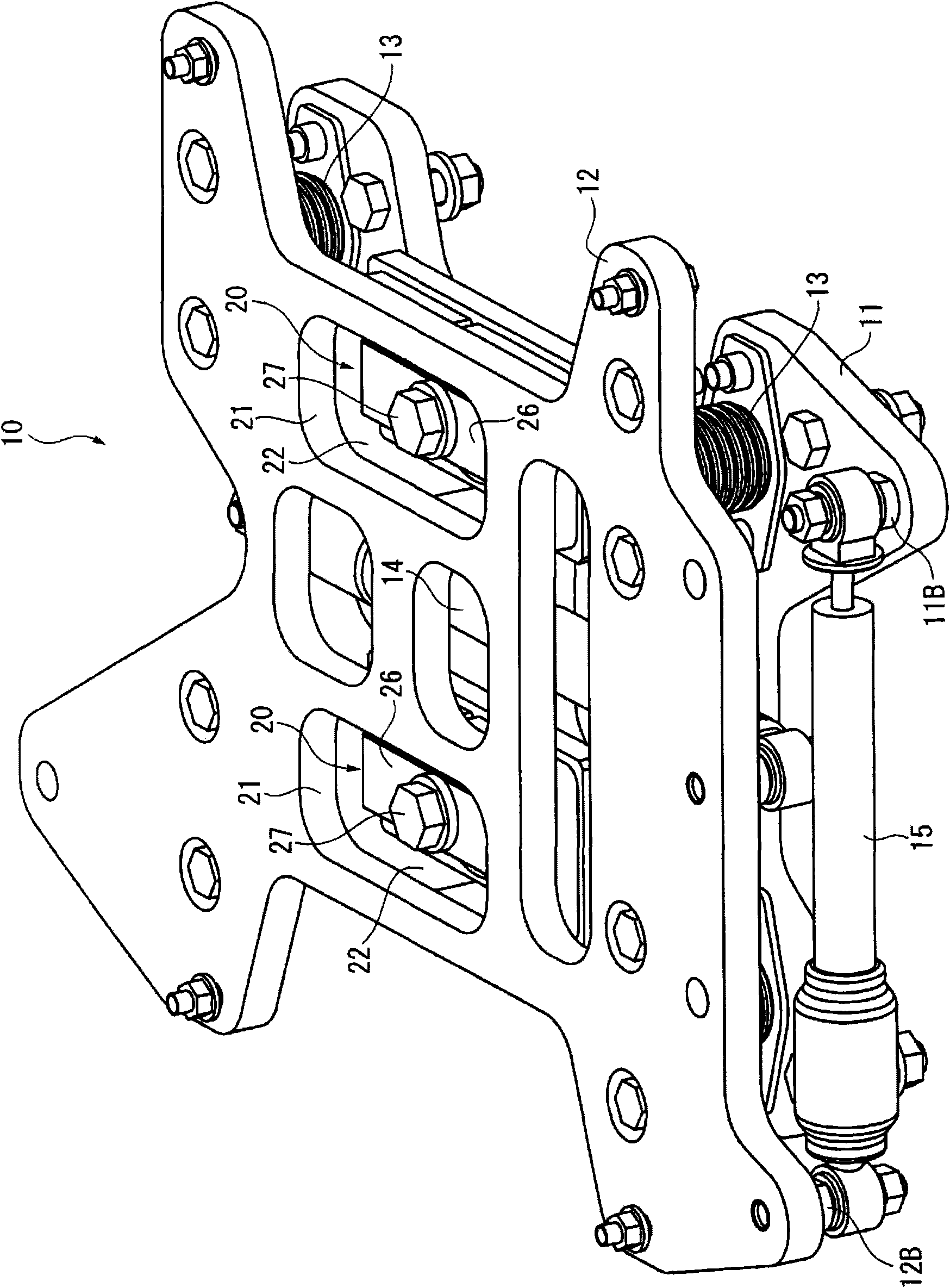
[0048] exist Figure 7 In the second embodiment shown in the perspective view of , the shock absorber 15 in the left-right direction is disposed inside the pair of laminated rubbers 13 on the front side. Specifically, the damper 15 is located on the front side with respect to the center of the front and rear laminated rubbers 13 , and is disposed close to the front laminated rubbers 13 . Regarding other structures, although there are differences in the specific shape of the lower support plate 11, the direction of the shock absorber 14 along the front-rear direction, etc., they are basically the same as those of the first embodiment described above.

[0049] Therefore, in this embodiment, since the arrangement positions of the shock absorbers 14 and 15 are also T-shaped, and the shock absorbers 15 are located on the front side compared to the center of the front and rear laminated rubber 13, the rear side stack can be reduced. The effect of the damping force of the layer rubb...


PUM


Abstract

A damping device (10) comprises laminated rubbers (13) interposed at four corners between a support having the floor plate of a construction machine and a movable body having the seat body of operator, and a pair of dampers (14, 15) having one end fixed to the lower supporting plate (11) on the support side and the other end fixed to the upper supporting plate on the movable body side.The laminated rubbers (13) are arranged while spaced apart in the front/back direction and the right/left direction with reference to the seating direction of the operator. One damper (14) is arranged along the front/back direction at a position corresponding to the center in the right/left direction between the laminated rubbers (13) arranged in the right/left direction, and the other damper (15) is arrangedalong the right/left direction on the front side of the center in the front/back direction between the laminated rubbers (13) arranged in the front/back direction.

Description

technical field [0001] The present invention relates to an anti-vibration device. Background technique [0002] At present, there is known a link mechanism for preventing the cab (cab) of construction machines such as hydraulic excavators and bulldozers from swinging left and right (for example, Patent Document 1). This link mechanism is a structure that connects the bottom surface of the driver's cab and the top surface of the frame supporting the driver's cab with a horizontal bar of an axle sleeper, and its advantage is that the structure is very simple. [0003] In addition, by connecting the cab and the frame up and down with elastic bodies such as rubber bushes or coil springs, and installing a shock absorber to attenuate the swing when the elastic body absorbs vibrations, it is possible to reduce the vibration during various operations such as digging or transporting earth and rocks. Shocks applied to the vehicle frame improve the operator's ride comfort in the cab. ...

Claims


Application Information

Patent Timeline
Patent Type & Authority Applications(China)
IPC IPC(8): E02F9/16F16F15/04B60N2/44B60N2/90
CPCF16F15/022F16F15/08E02F9/166E02F9/163B60N2/502B60N2/542
Inventor 中村晋也山下敏雄光田慎治田丸正毅伊藤博幸
Owner KOMATSU LTD
Why Eureka
Try Eureka