
Endoscope system

a technology of endoscope and endoscope, which is applied in the field of endoscope system, can solve the problems of large gap between the maneuver skill of an inexperienced physician and the skill of an experienced physician, and the effort required for hand feeding insertion work,

Active Publication Date: 2009-09-01
OLYMPUS CORP
View PDF18 Cites 70 Cited by
  • Summary
  • Abstract
  • Description
  • Claims
  • Application Information

AI Technical Summary

Benefits of technology

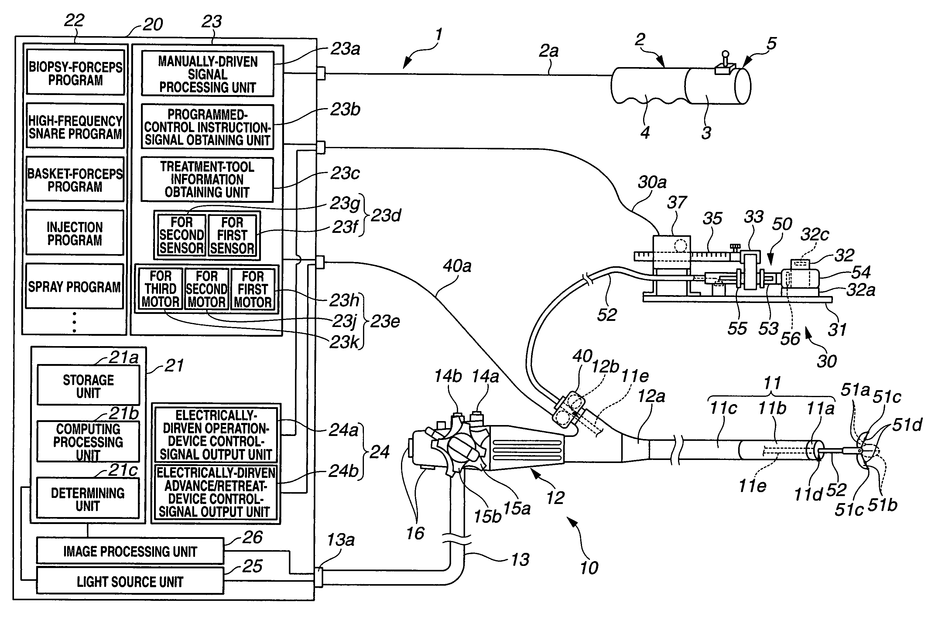
The endoscope system described in this patent has multiple treatment tools that can be inserted into the body cavity through the endoscope. The system also includes an electrically-driven operation device, an electrically-driven advance / retreat device, and a control device. The control device can be connected to the operation instructing device, which has two operating instruction units for placing the operation device in a manually-driven operating state or a programmed-control state. The control device can output a control signal to the operation device based on the first or second instruction signal. The technical effect of this invention is to provide a more efficient and effective endoscope system for treating various medical conditions.

Problems solved by technology

However, insertion work by hand feeding takes a lot of efforts.
Also, it takes considerable attention to insert, for example, a sheath portion reaching 2 m without buckling, and preventing the sheath portion from coming into contact with an unclean area, which has been troublesome and intricate work for a worker.
In other words, a huge gap is caused in maneuver skill between an inexperienced physician and an experienced physician.

Method used


Image

  • Endoscope system
  • Endoscope system
  • Endoscope system

Examples


Embodiment Construction

[0057]Hereinafter, embodiments of the present invention will be described with reference to the drawings.

[0058]One embodiment of the present invention will be described with reference to FIG. 1 through FIG. 16.

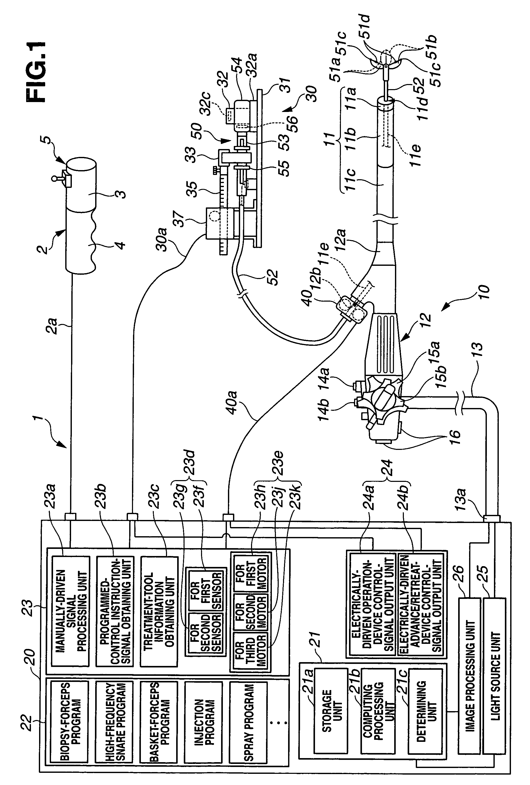
[0059]As illustrated in FIG. 1, an endoscope system 1 principally comprises an operation instructing device 2, an endoscope 10, a control device 20, a treatment-tool operation-unit electrically-driven operation device (hereinafter, referred to as electrically-driven operation device) 30, and a treatment-tool insertion-unit electrically-driven advance / retreat device (hereinafter, referred to as electrically-driven advance / retreat device) 40. With the present embodiment, the operation instructing device 2, control device 20, electrically-driven operation device 30, and electrically-driven advance / retreat device 40 make up an endoscope operation assisting device.

[0060]The endoscope 10 comprises an insertion unit 11, an operation unit 12, and a universal cord 13. The operation uni...


PUM


Abstract

An endoscope system comprises multiple types of treatment tools including a treatment-tool insertion unit, and a function unit having a function for performing treatment; an electrically-driven operation device which electrically drives the function unit; an electrically-driven advance / retreat device which electrically drives the treatment-tool insertion unit; a control device including at least one of a control unit for outputting a control signal to the electrically-driven advance / retreat device and the electrically-driven operation device, and an operating program corresponding to a treatment tool; and an operation instructing device including a first operating instruction unit for outputting an instruction signal for placing the electrically-driven operation device and the electrically-driven advance / retreat device into a manually-driven operating state, and a second operating instruction unit for outputting an instruction signal for placing the electrically-driven operation device and the electrically-driven advance / retreat device into a programmed-control state by the operating program. When receiving either of the signal from the first operating instruction unit or the signal from the second operating instruction unit, the control unit performs control for outputting the control signal corresponding to the received signal to at least one of the electrically-driven advance / retreat device and the electrically-driven operation device.

Description

BACKGROUND OF THE INVENTION[0001]1. Field of the Invention[0002]The present invention relates to an endoscope system including an endoscope operation assisting device for facilitating operation of various types of treatment tools to be used together with an endoscope.[0003]2. Description of the Related Art[0004]In recent years, endoscopes have been widely used in the medical-application field. An endoscope comprises a slender insertion unit, and an operation unit provided at the base of this insertion unit. Generally, a bending portion which is bendable is provided at the tip side of the slender insertion unit. A knob for bending and operating the bending portion, and various types of switches and so forth for performing various types of operations of endoscope functions are provided in the operation unit.[0005]With an endoscope to be employed for the medical-application field, when performing observation of a body cavity organ, an insertion unit is inserted into the body cavity of ...

Claims


Application Information

Patent Timeline
Patent Type & Authority Patents(United States)
IPC IPC(8): A61B1/00
CPCA61B1/018A61B1/32A61B17/29A61B17/32056A61B10/04A61B10/06A61B2019/2276A61B2017/00212A61B2017/2212A61B17/221A61B1/00133A61B2034/742
Inventor KOMIYA, TAKAAKIMURAKAMI, KAZUSHIICHIKAWA, HIROAKIONUKI, YOSHIOKURA, YASUHITONISHIIE, TAKEHIRO
Owner OLYMPUS CORP
Learn More