Mechanical advantage tourniquet

a technology of tourniquets and tourniquets, applied in the field of tourniquets, can solve the problems of affecting the efficiency with which a tourniquet can be applied to an injured appendage, affecting the efficiency of the tourniquet application, and without experience in the level of medical care to properly apply the tourniquet and effectively restrict the flow of blood, etc., to achieve efficient and effective compression of an injured appendage, fast and easy application, and quick and easy application

Inactive Publication Date: 2009-09-01
PYNG MEDICAL CORP
View PDF11 Cites 77 Cited by
  • Summary
  • Abstract
  • Description
  • Claims
  • Application Information

AI Technical Summary

Benefits of technology

[0008]Using the soldier as an example, the mechanical advantage tourniquet is designed for a fast and easy application as required by the soldier under tremendous pressure and / or in shock, and the need to quickly apply and tighten a tourniquet on his own body, with possibly one hand, in approximately five seconds. As such, the device is a continuous strap, and not pre-looped to allow use in the field by a soldier whose leg or legs may be trapped or obstructed. The bionics of the mechanical advantage tourniquet of the present invention, can more efficiently and effectively compress an injured appendage, thereby temporarily stopping the flow of blood.
[0009]The tourniquet of the present invention is lightweight and portable so that it can be carried in a pocket of a soldier's uniform and is designed so that a weak and / or wounded soldier can apply it in the field or under combat conditions. For example, the soldier can apply the tourniquet while wearing gloves and the tourniquet is effective over rain and snow gear. Further the tourniquet can have luminescent markings to make it easy to use in at night or in a darkened environment. The tourniquet is also self-contained with no additional pieces or assembly required. Further, the tourniquet can be easily and successfully applied to the body under adverse weather conditions, such as in extreme temperatures ranging from at least +40 degrees to 125 degrees F., in and around ice, snow, rain, mud, saltwater, blowing sand and dirt, and other environmental obstacles. The tourniquet can also withstand all standard consumer product impact tests.
[0010]The present invention includes a tourniquet or pressure control apparatus for restricting a flow of blood through or from a body part, the apparatus including at least one arcuate member which can be a base member or a C-clip, for example, for attaching to the body part. The arcuate member has a first end and an opposite second end. A primary tightening device including a mechanical advantage power system can be mounted on the at least one arcuate member for adjusting a pressure of the apparatus on the body part. A secondary tightening device or cinch strap can be disposed on at least a portion of the arcuate member for circumferentially tightening the apparatus on the body part. A locking device can securely close the apparatus around the body part by being attached to the arcuate member.
[0011]The primary tightening device includes a mechanical advantage power system that can multiply an output force while minimizing the input force needed to create the output force. Such mechanical advantage power systems include, but are not limited to pulleys, eyelets, post systems, needle bobbins, gears, levers, wheels, and cams.

Problems solved by technology

However, a tourniquet is often applied as an emergency measure by individuals with knowledge that a tourniquet must be used, yet without experience in the level of medical care to properly apply the tourniquet and effectively restrict the flow of blood.
The state of mind in which individuals applying and / or receiving the tourniquet may find themselves include shock, anxiety and desperation.
Further, environmental conditions, such as the rain, snow, sandstorm, or dust storm also affect the efficiency with which a tourniquet can be applied to an injured appendage.

Method used


Image

  • Mechanical advantage tourniquet
  • Mechanical advantage tourniquet
  • Mechanical advantage tourniquet

Examples


first embodiment

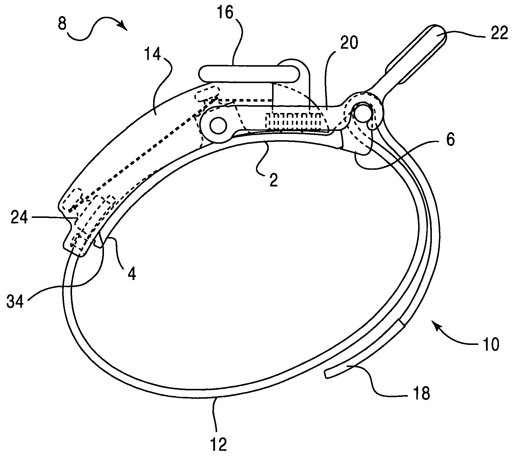
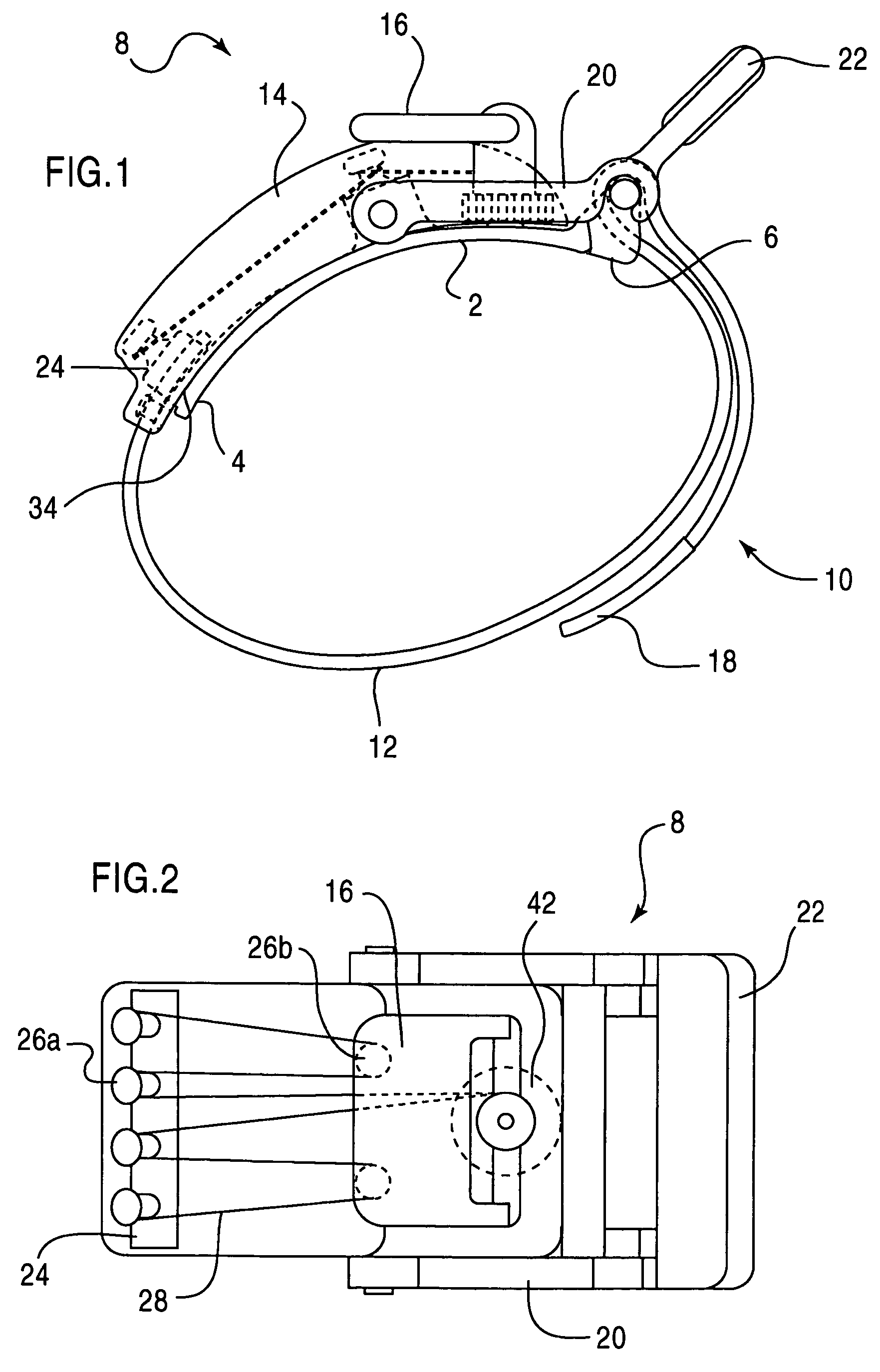
[0027]FIG. 1 illustrates a side view of the mechanical advantage tourniquet 10 according to the present invention. As shown in FIG. 1, the tourniquet 10 includes a mechanical advantage power system 8, an arcuate member or base 2, a strap 12, and a locking member 20.

[0028]The base 2 has a first end 4 and a second end 6, and serves as a mounting means for mounting the tourniquet 10 onto the injured appendage. The base 2 can be formed from a flexible material, including but not limited to, a polymeric material such as acetal or nylon.

[0029]The strap 12, such as a cinch strap is an elongated member that can also be formed from any suitably flexible material including, but not limited to, nylon. The strap 12 extends from the first end 4 of the base 2 around the injured appendage where it is threaded through and locked into place by the locking member 20. In combination, the strap 12, along with the mechanical advantage power system 8, serve as tightening means for tightening the tourniqu...

second embodiment

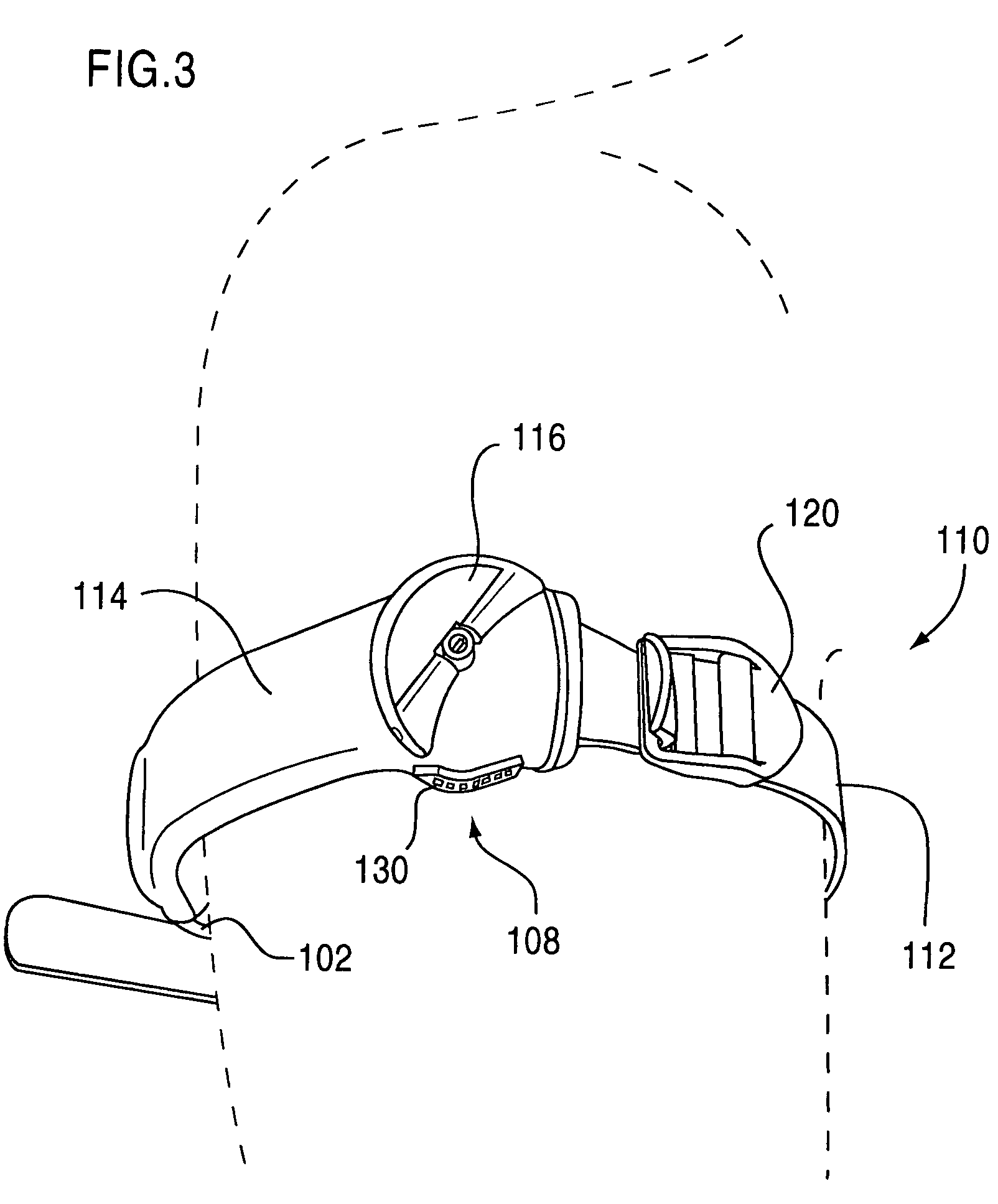
[0038]FIGS. 3-6 illustrate the mechanical advantage tourniquet 110 according to the present invention, which includes components designed to apply a controlled pressure to the injured appendage and thereby restrict the flow of blood through or from the injury. As disclosed above, the mechanical advantage is a device that can multiply an output force while reducing an input force needed to create the output force. FIG. 3 illustrates the mechanical advantage tourniquet 110 as it can be applied to an injured appendage. The tourniquet 110 includes an arcuate member or C-clip 102 on which is mounted a mechanical advantage power system 108 having a tightening turnkey 116 for activating the mechanical advantage, and a release button 130 for canceling the mechanical advantage, a strap 112, and a locking member 120.

[0039]A shroud 114, shown in FIG. 3, is a sleeve-like member that extends circumferentially around an outer surface of the C-clip 102 and acts as a barrier to prevent foreign elem...


PUM


Abstract

A pressure control apparatus for restricting a flow of blood through or from a body part includes at least one arcuate member for attaching to the body part. The at least one arcuate member has a first end and an opposite second end. The first end includes a hook for fastening to a buckle mounted at the opposite second end. A mechanical advantage power system includes a turnkey and is connected to the at least one arcuate member and serves to adjusting a pressure of the apparatus on the body part by turning the turnkey. An elongated strap is disposed on at least a circumferential portion of the arcuate member for circumferentially tightening the apparatus around the body part. A locking device closes the apparatus around the body part and is attached to the at least one arcuate member. A cover or shroud is disposed on an outer perimeter of the at least one arcuate member for enclosing a portion of the mechanical advantage power system.

Description

[0001]This application claims priority to applicants' copending U.S. Provisional Application Ser. No. 60 / 509,917 entitled “MECHANICAL ADVANTAGE TOURNIQUET” filed Oct. 10, 2003, and U.S. Provisional Application No. 60 / 615,027 entitled “MECHANICAL ADVANTAGE TOURNIQUET III (C-CLAMP VERSION)” filed Oct. 4, 2004. The entirety of these patent applications is incorporated herein by reference.BACKGROUND OF THE INVENTION[0002]1. Field of the Invention[0003]The present invention relates to a tourniquet with an improved tightening system that provides a mechanical advantage for applying a compression force to an appendage.[0004]2. Description of the Related Art[0005]A tourniquet is a device for temporarily controlling the flow of blood through or from a large artery in an appendage under emergency conditions as the tourniquet cuts off the blood supply to the appendage for a period of time. Although primarily used as a first-aid or triage measure, tourniquets can also be used in a medical facil...

Claims


Application Information

Patent Timeline
Patent Type & Authority Patents(United States)
IPC IPC(8): A61B17/00A61BA61B17/132
CPCA61B17/1327A61B17/1322
Inventor HEINZ, THOMAS J.RUMSEY, ROYCEBANNISTER, EDCHAN, SAI CHUNG
Owner PYNG MEDICAL CORP
Why Eureka
Try Eureka