Electrical junction box with a built-in fitting insert

a technology of electric junction box and built-in fitting, which is applied in the direction of machine supports, electrical apparatus casings/cabinets/drawers, coupling device connections, etc., can solve the problems of insufficient electrical ground, waste of time and money, and installation involves needless steps

Inactive Publication Date: 2009-09-01
YAN FR SHAOCHONG
View PDF11 Cites 30 Cited by
  • Summary
  • Abstract
  • Description
  • Claims
  • Application Information

AI Technical Summary

Benefits of technology

[0009]An object of the invention is to provide for a secure ground between the Electrical Junction Box and the metal armor of the armored metal cable. A second object of the invention is to provide an Electrical Junction Box which can firmly hold the armored metal cable in place without the use of an internal clamp or fastener, thereby increasing the carrying capacity of the Electrical Junction Box. A third object of the invention is to create an Electrical Junction Box with easier access, after installation of an extension ring, switch or receptacle, to the means used to secure the armored metal cable to the Electrical Junction Box.

Problems solved by technology

A problem with the current design of Electrical Junction Boxes is that the installation involves needless steps.
This wastes time and money.
Another problem with the current design is that if the armored metal cable is not properly seated in the Electrical Junction Box, the electrical ground might be inadequate.
Also, the armored metal cable will not be securely held in place if the clamp is not properly seated.
Another problem encountered with Electrical Junction Boxes as presently configured is that the Electrical Junction Boxes are commonly used with Extension Rings (mud-rings) mounted prior to installation of the armored metal cable, which can make fastening of the clamp awkward or difficult.
An additional problem associated with presently configured Electrical Junction Boxes is that the clamps used to hold the armored metal cable in place are located in the interior of the Electrical Junction Box, thus decreasing the volume of the cavity of the Electrical Junction Box.

Method used


Image

  • Electrical junction box with a built-in fitting insert
  • Electrical junction box with a built-in fitting insert
  • Electrical junction box with a built-in fitting insert

Examples


Embodiment Construction

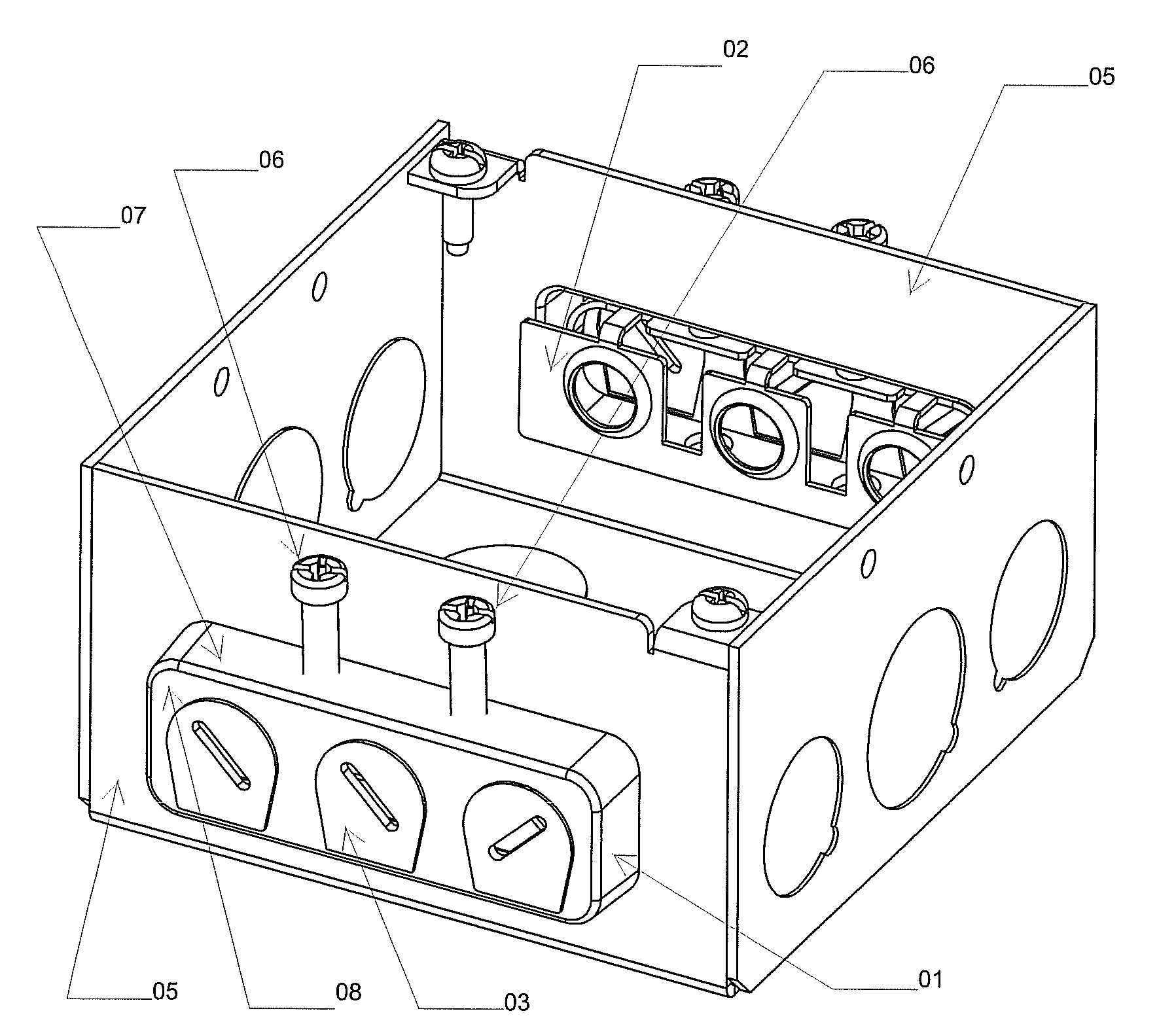
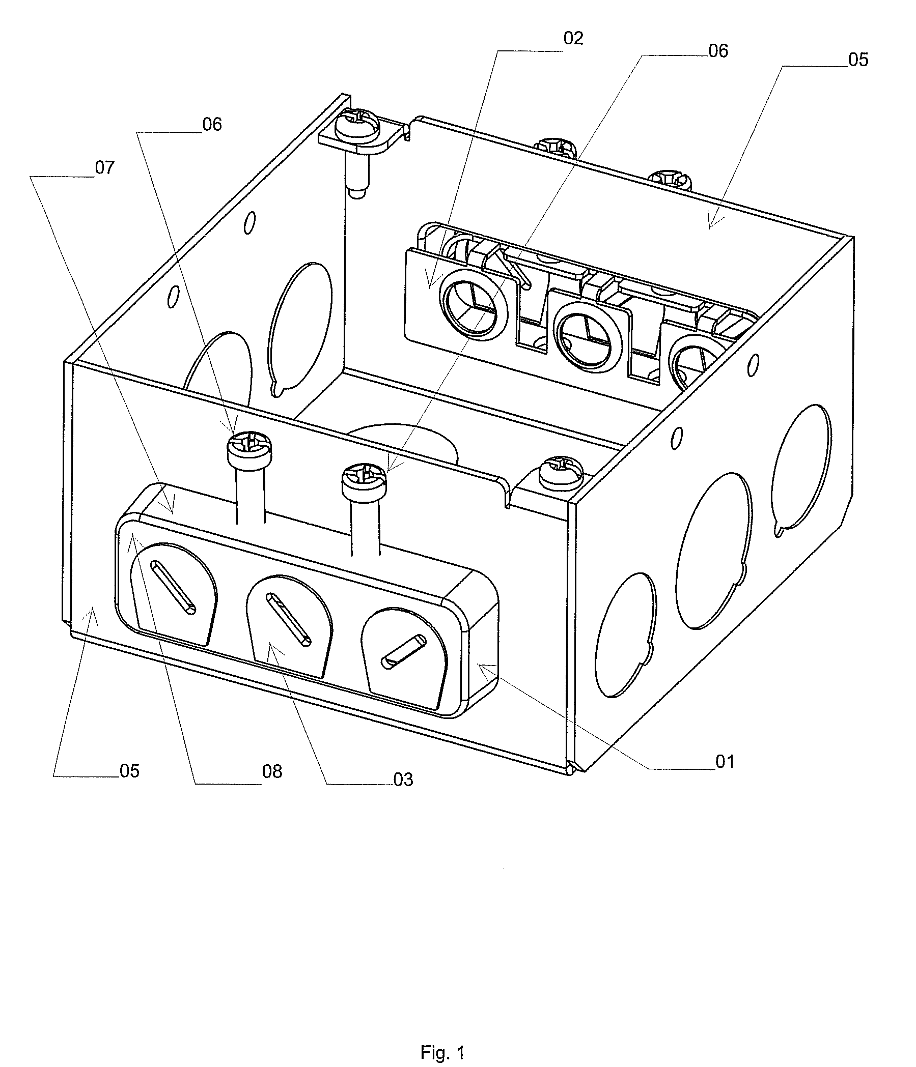
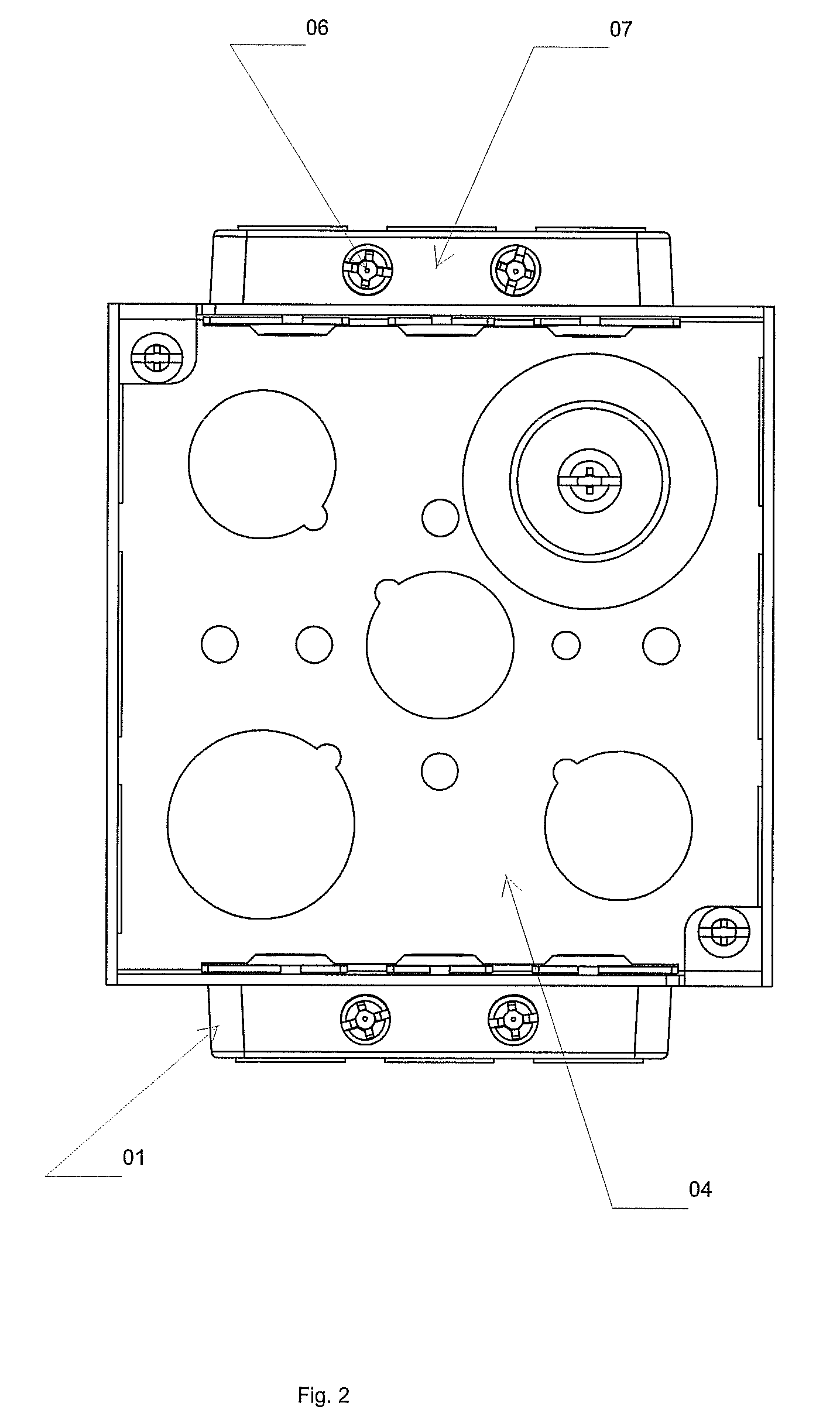
[0008]This invention relates to an Electrical Junction Box with a Built-in Fitting and clamp external to the Electrical Junction Box, that allows for a secure grounding path while firmly holding an armored metal cable in position. Electrical Junction Boxes come in a variety of different shapes, but are typically rectangular in shape. The Electrical Junction Box typically has a cavity formed by side walls (05) and a back wall (04). The cavity holds wiring, switches or receptacles. The Electrical Junction Box will contain a number of pry-outs (03) in the side walls or back wall. Electrical power is run to the Electrical Junction Box via wires contained in armored metal cable. The armored metal cable is connected to the Electrical Junction Box at the pry-out. In the preferred embodiment, the Electrical Junction Box is constructed with an extruded Built-in Fitting (01). The Built-in Fitting has a plurality of side walls (07) and a back wall (08), and is generally a rectangular shaped bo...


PUM


Abstract

This invention relates to an Electrical Junction Box with an external Built-in Fitting and clamp for securing armored metal cable to the Electrical Junction Box. The Built-in Fitting is extruded from a side wall of the Electrical Junction Box and has at least one pry-out for receiving an armored metal cable. A clamp is attached to the Built-in Fitting with threaded fasteners. As the threaded fasteners are tightened, the armored metal cable is clamped in the opening of the side wall of the Built-in Fitting.

Description

BACKGROUND OF THE INVENTION[0001]Typically, in construction of commercial, industrial and some residential space, building codes require the use of armored metal cable, for holding electrical wires, which terminate at an Electrical Junction Box. The armored metal cable is affixed to the interior of the Electrical Junction Box by a removable clamp, nut or other connector which is installed in the interior of the box. A variety of electrical switches and receptacles can be mounted inside the Electrical Junction Box. Often, when shipped to the job site, the Electrical Junction Box already has an electrical switch or receptacle mounted onto the box. A laborer, in installing the armored metal cable, must first remove the switch or receptacle, remove a pry-out from the Electrical Junction Box, run the armored metal cable through the pry-out into the interior of the Electrical Junction Box, install the clamp to hold the armored metal cable in place and then reinstall the switch or receptac...

Claims


Application Information

Patent Timeline
Patent Type & Authority Patents(United States)
IPC IPC(8): H02G3/08H02G3/18
CPCH02G3/0666H02G15/064H02G3/083
Inventor YAN, FRANK SHAOCHONG
Owner YAN FR SHAOCHONG
Why Eureka
Try Eureka