Electronic component series

a technology of electronic components and components, applied in the field of electronic components, can solve the problems of poor mounting efficiency and inability to smoothly mount electronic components on circuit boards or the like, and achieve the effect of suppressing vibration of electronic components

Active Publication Date: 2009-09-08
TDK CORPARATION
View PDF23 Cites 9 Cited by
  • Summary
  • Abstract
  • Description
  • Claims
  • Application Information

AI Technical Summary

Benefits of technology

[0007]With the foregoing in view, an object of the present invention is to provide an electronic component series which can sufficiently suppress vibration of the electronic components when the cover tape is peeled from the carrier tape.
[0010]With this electronic component series, at least one of the pair of adhesive regions has an adhesive width which cyclically increases in size depending on the corresponding storage recess. Therefore, the peel strength of the cover tape in the first adhesive regions can be sufficiently increased so that the difference between the peel strength of the cover tape in the first adhesive regions and the peel strength of the cover tape in the second adhesive regions can be sufficiently reduced. Therefore, when the cover tape is peeled from a carrier tape, vibration occurring in the storage recesses of the carrier tape can be suppress and vibration of the electronic components can also be suppressed.
[0011]With this electronic component series, at least one of the pair of adhesive regions has a plurality of first adhesive regions cyclically established corresponding to plurality of the storage recesses respectively, and second adhesive regions established between the plurality of first adhesive regions. The adhesive area of the first adhesive regions is preferably larger than the adhesive area of the second adhesive regions. In this case, the difference between the peel strength of the cover tape in the first adhesive region and the peel strength of the cover tape in the second adhesive region can be sufficiently reduced. Therefore, vibration which occurs in the storage recesses of the carrier tape when the cover tape is peeled off of the carrier tape can be more sufficiently suppressed, and vibration of the electronic components can also be more sufficiently suppressed.
[0013]In this case, vibration of the electronic components while peeling the cover tape from the carrier tape can be very effectively suppressed as compared to the case where the ratio between the adhesive area of the first adhesive regions and the adhesive area of the second adhesive regions is greater than 0.6.
[0015]With the electronic component series of the present invention, vibration of the electronic components can be suppressed when peeling the cover tape from the carrier tape.

Problems solved by technology

However, with the electronic series shown in the aforementioned reference, the carrier tape is strongly vibrated when the cover tape is peeled off of the carrier tape, and the electronic components will be vibrated and tilted or may even be scattered from the storage recesses by this strong vibration.
Therefore, when the cover tape is peeled off of the carrier tape and the electronic components in the storage recesses are quickly removed by attaching or the like, mounting of the electronic components onto a circuit board or the like will not proceed smoothly, and the mounting efficiency may be poor.

Method used


Image

  • Electronic component series
  • Electronic component series
  • Electronic component series

Examples


embodiments 1 through 5

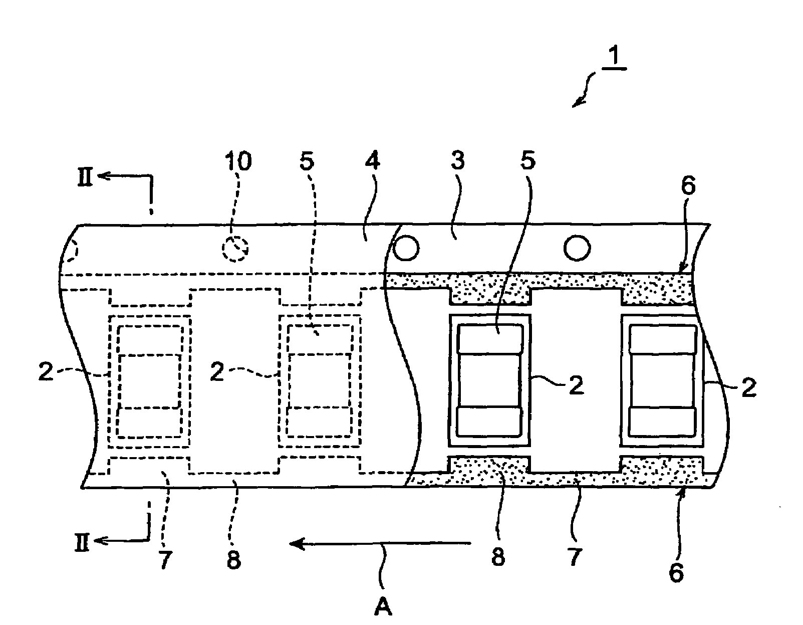
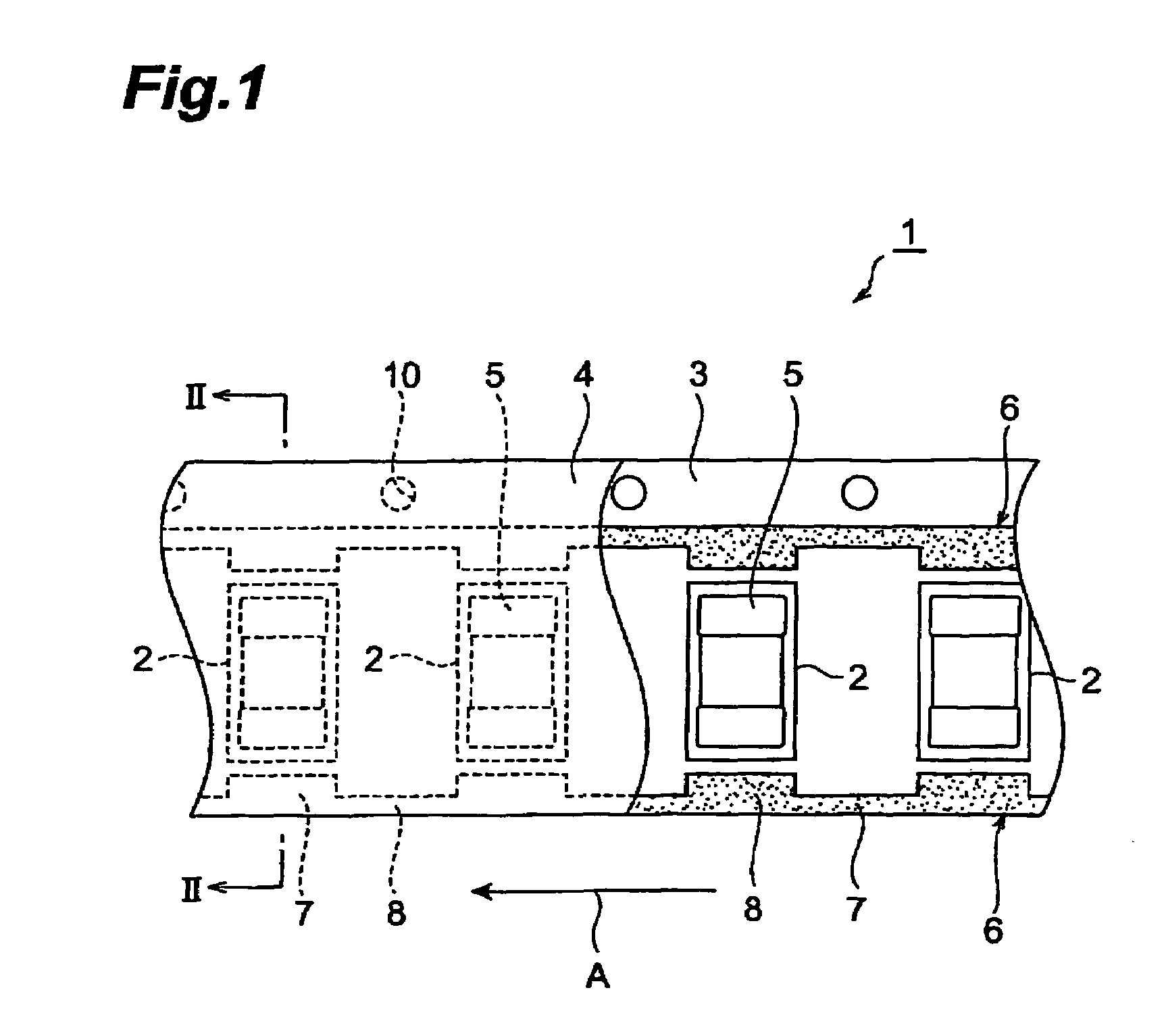
[0041]A laminate paper was prepared for use as the carrier tape. Press working of this laminate paper was performed in order to form a plurality of storage recesses in the longitudinal direction. At this time, the plurality of storage recesses were cyclically formed at a fixed interval. The size of the storage recess was 680 μm×380 μm×350 μm.

[0042]Next, C0603 size multilayer capacitors were stored as the electronic components in each of the storage recesses of the carrier tape.

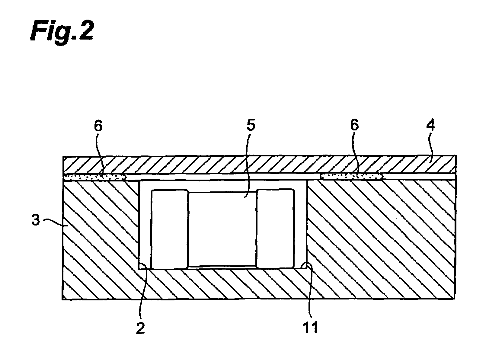
[0043]On the other hand, a polyester cover tape (width 5.25 mm, thickness 0.053 mm) was prepared by coating the whole surface of one side with an acrylic type adhesive.

[0044]Next, the cover tape was placed over the surface of the carrier tape where the plurality of storage recesses were formed, with the surface where the adhesive was applied facing the carrier tape.

[0045]Next, a beating roller (width 0.5 mm) was brought into contact with the surface of the cover tape in a position to enclose the storage recess...

embodiments 6 through 10

[0051]Electronic component series were manufactured to be identical to embodiment 1 except that the electronic components were replaced with C0402 size electronic components and the size of the storage recess was 450 μm×250 μm×240 μm. The attachment rate for the electronic component series obtained in this manner was calculated in the same manner as for embodiment 1. The results are shown in Table 1.

[0052](Comparison 2)

[0053]An electronic component series was manufactured to be identical to comparison 1 except that the electronic components were replaced with C0402 size electronic components and the size of the storage recess was 450 μm×250 μm×240 μm. The attachment rate for the electronic component series obtained in this manner was calculated in the same manner as for embodiment 1. The results are shown in Table 1.

[0054]From the results shown in Table 1, the electronic component series of embodiments 1 through 5 were found to have sufficiently higher attachment rates than the elec...


PUM


Abstract

The present invention is an electronic component series, comprising a carrier tape which has a plurality of storage recesses cyclically arranged along the longitudinal direction, electronic components to be stored in the plurality of storage recesses, a cover tape established to cover the plurality of storage recesses of the carrier tape, and a pair of adhesive regions which adhere to the carrier tape and to the cover tape, and extend along the longitudinal direction of the carrier tape so as to enclose the plurality of storage recesses from both sides, wherein the adhesive width of the pair of adhesive regions is cyclically increased in size corresponding to the storage recesses respectively. With this electronic component series, the difference in the peel strength of the cover tape between the first adhesive regions and the second adhesive regions can be sufficiently reduced.

Description

BACKGROUND OF THE INVENTION[0001]1. Field of the Invention[0002]The present invention relates to an electronic component series which stores a plurality of electronic components.[0003]2. Related Background Art[0004]Electronic component series are known for storing a plurality of electronic components. These electronic component series are comprising a carrier tape which has a plurality of storage recesses cyclically arranged along the longitudinal direction, various electronic components which are stored in the plurality of storage recesses, a cover tape established to cover the plurality of storage recesses of the carrier tape, and a pair of adhesive regions which adhere to the carrier tape and the cover tape.[0005]A commonly known conventional electronic component series is presented in Japanese Patent Application Laid Open No. 2001-163305. The electronic component series shown in this reference has a pair of rail-like adhesive regions which extend so as to enclose the plurality o...

Claims


Application Information

Patent Timeline
Patent Type & Authority Patents(United States)
IPC IPC(8): B65D85/00
CPCH05K13/0084Y10S206/813
Inventor YOSHII, AKITOSHIAHIKO, TAISUKESUDA, TOORUTAKASHIMA, TSUYOSHIIZUMIBE, YASUSHI
Owner TDK CORPARATION
Why Eureka
Try Eureka