Rotor blade for a wind power station

a technology for wind power stations and rotor blades, which is applied in the direction of liquid fuel engines, vessel construction, marine propulsion, etc., can solve the problems of cross-flow and interfere with the effective airflow around the rotor blade, and achieve the effect of improving aerodynamic airflow

Inactive Publication Date: 2009-09-08
SENVION GMBH
View PDF17 Cites 45 Cited by
  • Summary
  • Abstract
  • Description
  • Claims
  • Application Information

AI Technical Summary

Benefits of technology

[0009]The objective of the present invention is to create a wind-driven power-plant rotor blade that offers substantially improved aerodynamic airflow around the blade.

Problems solved by technology

Moreover the cross-flow also interferes with the effective airflow around the rotor blade because of the generation of turbulences that entail premature airflow detachment.

Method used


Image

  • Rotor blade for a wind power station
  • Rotor blade for a wind power station
  • Rotor blade for a wind power station

Examples


Embodiment Construction

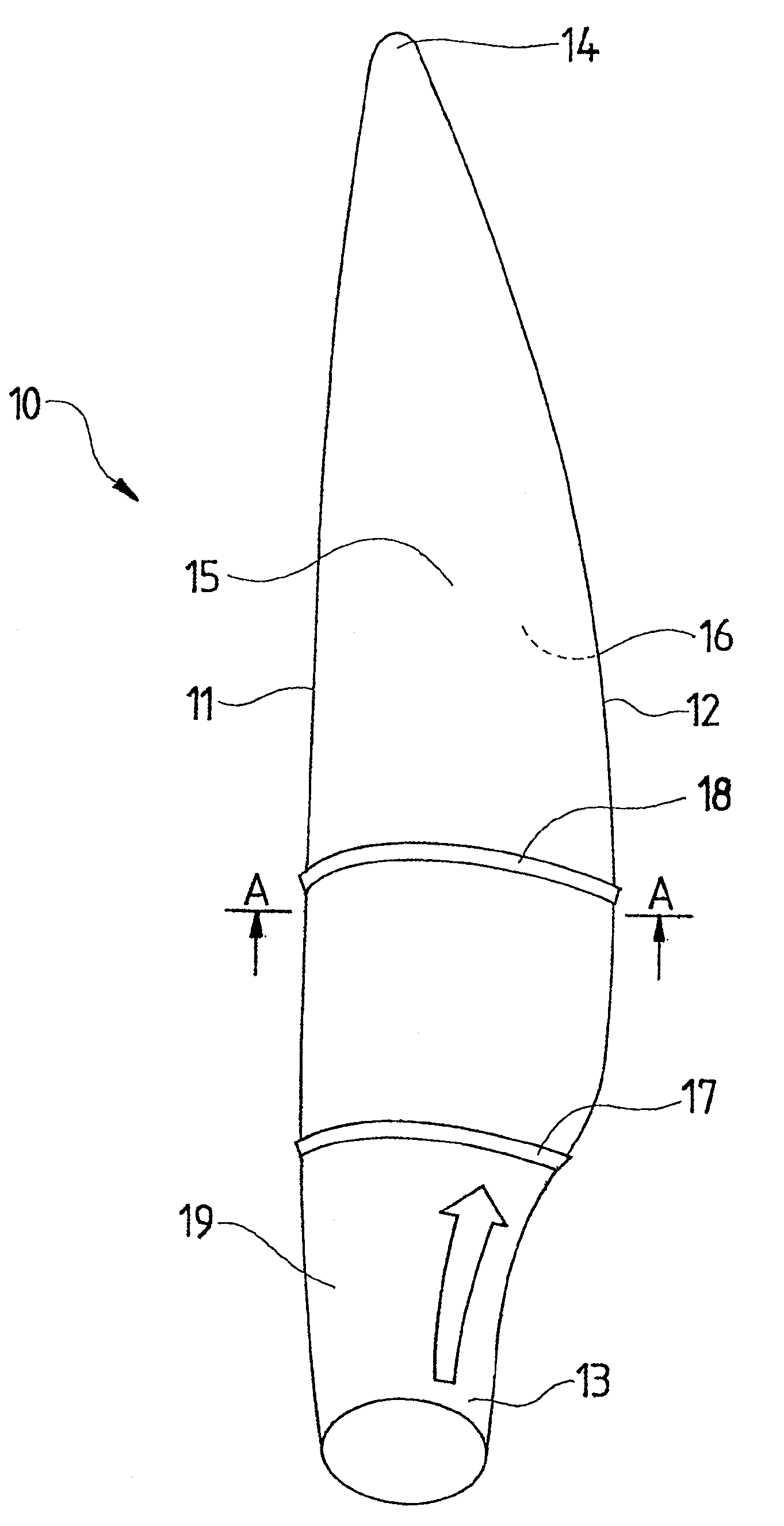
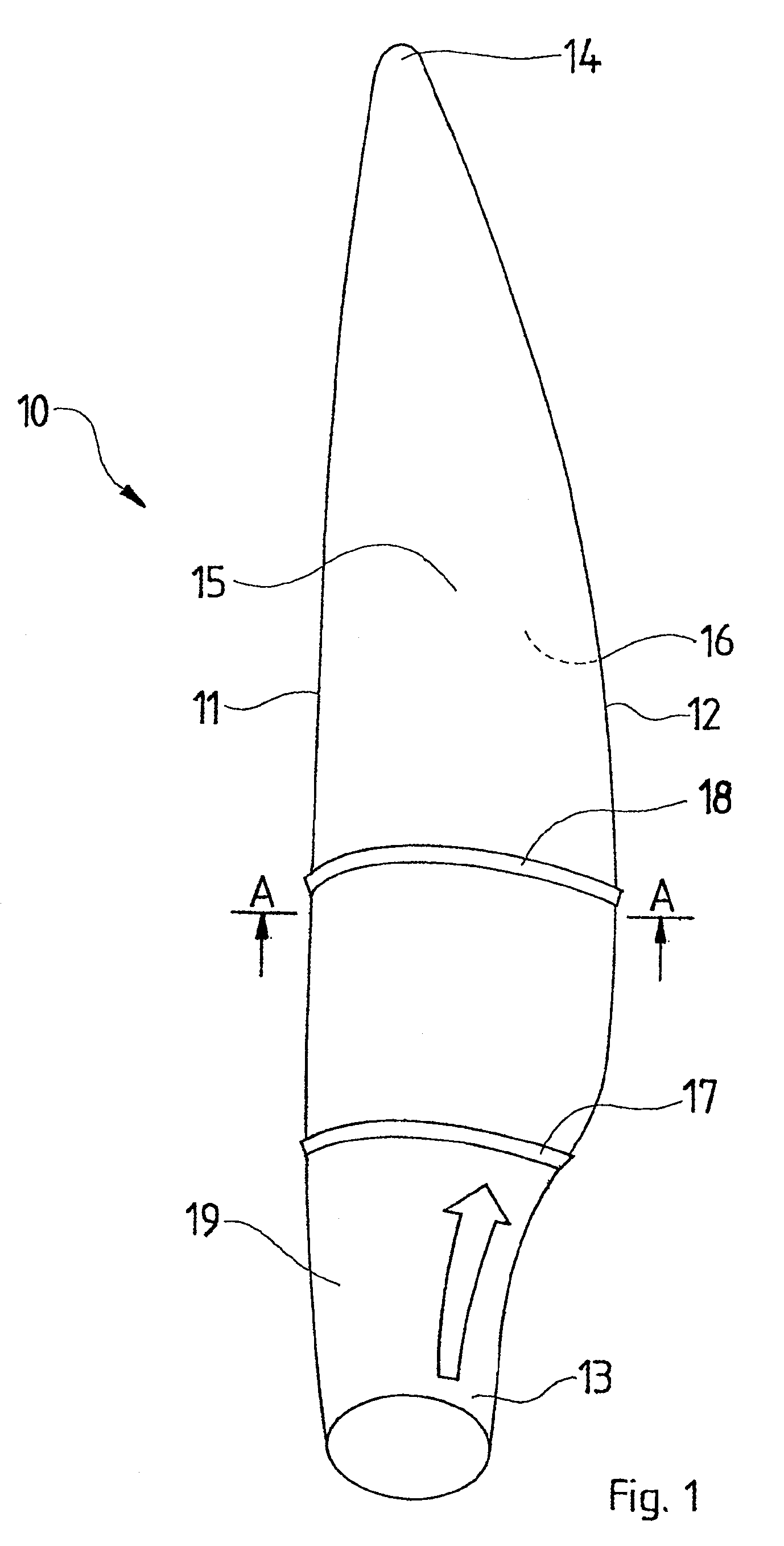
[0037]FIG. 1 shows a rotor blade 10 having a leading edge 11, a trailing edge 12, a blade root 13, a blade tip 14, a suction side 15 and a pressure side 16. The relative thickness of the rotor blade decreases towards the outside from the blade root 13 to the blade tip 14. The leading edge 11 points in the direction of rotation of the rotor blade. Planar elements 17 and 18 are mounted in the direction of airflow at the suction side 15 and suppress cross-flows on the suction side 15 and preclude premature airflow detachment. A transition range 19 is characterized in that the contour of the blade root 13, which in this instance is cylindrical, merges into a pear-shaped, lift-generating contour. An arrow denotes the cross-flow.

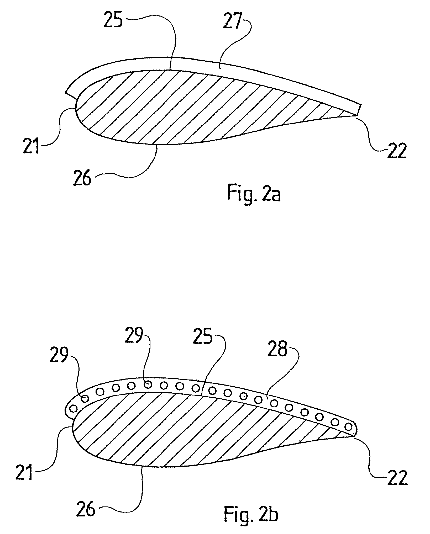
[0038]FIG. 2a shows a section of the rotor blade along line A-A of FIG. 1, the blade having a leading edge 21, a trailing edge 22, a suction side 25 and a pressure side 26. The planar element 27 is mounted on the suction side 25 and runs from the leading edge 21 t...


PUM


Abstract

A rotor blade for a wind power station includes a profiled member that is provided with a relative thickness which decreases towards the outside from a root to a tip of the blade. The profiled member has a leading edge and a trailing edge as well as a suction side and a pressure side while generating a negative pressure relative to the pressure side on the suction side when being flown against by moved air, the negative pressure resulting in buoyancy. The suction side of the rotor blade encompasses a device for optimizing flow around the profiled member. The device is provided with at least one planar element that extends substantially in the direction of flow, protrudes from the suction side, and is arranged in the zone of a transversal flow which runs from the root to the tip of the blade on the suction side of the profiled member.

Description

BACKGROUND OF THE INVENTION[0001]1. Field of the Invention[0002]The present invention relates to a rotor blade for a power-plant fitted with a device optimizing aerodynamics.[0003]2. Description of Related Art[0004]Wind-driven power-plants comprise a rotor fitted with one or more rotor blades. Each rotor blade in turn comprises a sectional blade contour, which is perpendicular to the blade's direction from blade root to blade tip, and of which the thickness decreases toward the outside, from the blade root toward the blade tip. The blade contour entails a suction side and a pressure side, so that when air is moving around the blade, the suction side is at a lower pressure than the pressure side. The pressure differential across the pressure and suction sides generates lift causing the rotor rotation, which in turn is used to drive an electric power generator.[0005]High rotor efficiency and hence high wind-driven power-plant output assumes, as smooth as possible, an airflow around th...

Claims


Application Information

Patent Timeline
Patent Type & Authority Patents(United States)
IPC IPC(8): F03D1/06
CPCF03D1/0633F03D1/0675Y02E10/721F05B2240/301Y02E10/72
Inventor QUELL, PETERPETSCHE, MARC
Owner SENVION GMBH
Why Eureka
Try Eureka