Electronically commutated motor and method for controlling the same

a technology of electronic commutation and motor, which is applied in the direction of multiple motor speed/torque control, synchronous motor starter, single motor speed/torque control, etc., can solve the problems of working point displacement into the desired region, transistor conductivity, etc., and achieve the effect of reducing commutation nois

Active Publication Date: 2009-09-08
ELEKTROSIL SYST DER ELEKTRONIK
View PDF29 Cites 26 Cited by
  • Summary
  • Abstract
  • Description
  • Claims
  • Application Information

AI Technical Summary

Benefits of technology

[0004]It is the object of the present invention to reduce commutation noise. This object is achieved by a motor in which a respective field-effect transistor (FET) controls the current through each stator winding phase, and a further component influences the working range of the FET to make the current through the winding phase substantially current while that phase is energized. In a preferred method, the FET is operated as a pinch-off current source.

Problems solved by technology

This control action results in a change in the conductivity of the transistor, which results in a displacement of the working point into the desired region.

Method used


Image

  • Electronically commutated motor and method for controlling the same
  • Electronically commutated motor and method for controlling the same
  • Electronically commutated motor and method for controlling the same

Examples


Embodiment Construction

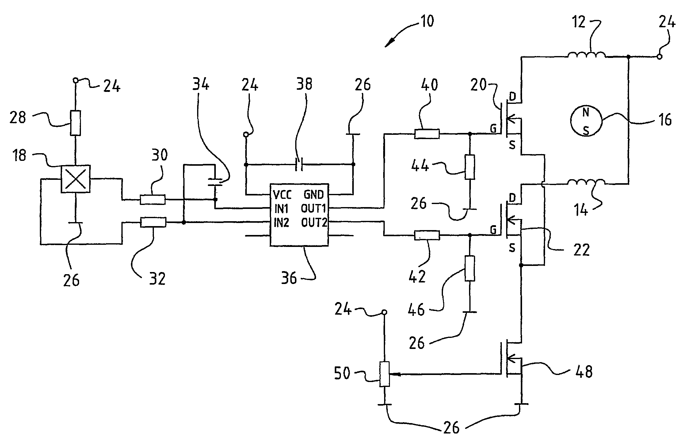
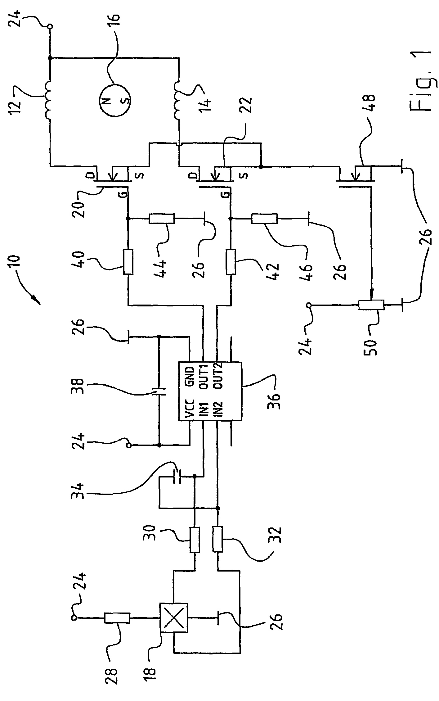
[0016]FIG. 1 is an exemplary depiction of a two-phase electric motor that can be used with the present invention. The electronically commutated DC motor 10 comprises two stator winding phases 12, 14 and a permanent-magnet rotor 16 (depicted merely symbolically). Arranged in the vicinity of rotor 16 is a Hall sensor 18. For reasons of clarity, the latter is illustrated at a different location in the present circuit diagram. Phase 12 is in series with a first power-stage transistor 20 (MOSFET), and phase 14 is in series with a second power-stage transistor 22 (MOSFET). Phases 12, 14 are connected to a positive lead 24. Positive lead 24 and negative lead 26 are connected, during operation, to a power supply (not depicted) or to a battery. Phases 12, 14 are usually coupled to one another in transformer fashion via the iron of the stator lamination stack.

[0017]Hall sensor 18 is connected on the one hand via a resistor 28 to positive lead 24, and on the other hand to negative lead 26. The...


PUM


Abstract

The invention relates to an electronically commutated motor (10) and to a method of controlling an electronically commutated motor (10). In order to reduce commutation noise, it is proposed to influence the working range of the power-stage transistors (20, 22) with the aid of a component (48), in such a way that each transistors produces, during energization of each respective stator winding, a substantially constant current through the stator winding (12, 14). Preferably, each power-stage transistor operates within a pinch-off range.

Description

CROSS-REFERENCE[0001]This application is a section 371 of PCT / EP2004 / 014759, filed 28 Dec. 2004, published 18 Aug. 2005 as WO 2005 / 076 456-A1. It also claims priority from German application DE 10 2004 006 449.0, filed 3 Feb. 2004, the entire content of which is hereby incorporated by reference.FIELD OF THE INVENTION[0002]The invention relates to an electronically commutated motor and to a method for controlling an electronically commutated motor.BACKGROUND[0003]With such motors, the occurrence of commutation noise is problematic for a number of applications. A number of suggested solutions to this are known from the existing art. A characteristic common to all the suggested solutions is that they are very complex and cost-intensive.SUMMARY OF THE INVENTION[0004]It is the object of the present invention to reduce commutation noise. This object is achieved by a motor in which a respective field-effect transistor (FET) controls the current through each stator winding phase, and a furt...

Claims


Application Information

Patent Timeline
Patent Type & Authority Patents(United States)
IPC IPC(8): H02P6/00H02P6/08H02P6/10
CPCH02P6/008H02P6/10H02P6/085H02P6/08H02P6/26
Inventor DORNHOF, KONSTANTIN
Owner ELEKTROSIL SYST DER ELEKTRONIK
Why Eureka
Try Eureka