Network device providing multi-function status indicators

a network device and status indicator technology, applied in the field of networked systems, can solve the problems of limited number of leds that may ultimately be implemented, difficulty for users to discern the actual parameters displayed by the leds, and increase the complexity of networked computing systems

Inactive Publication Date: 2009-09-08
CISCO TECH INC
View PDF5 Cites 4 Cited by
  • Summary
  • Abstract
  • Description
  • Claims
  • Application Information

AI Technical Summary

Problems solved by technology

Unfortunately, such implementations typically provide only a relatively small front panel area where LED display panels may be located to facilitate convenient inspection of the status of various parameters indicated on the device.
However, as networked computing systems increase in complexity, individual network devices may be required to display status information pertaining to increasing numbers of parameters corresponding to, for example, increased numbers of ports or system information.
Indeed, because of the small form factor of many network devices, only a limited number of LEDs may ultimately be implemented on the display panel.
Moreover, if the number and spatial density of LEDs provided on the display panel becomes too large, it may become difficult for users to discern the actual parameters displayed by the LEDs.
However, such an approach can limit the ability of users to conveniently monitor the status of other parameters not shown on the LED display panel.
Unfortunately, because the particular status information displayed by such implementations depends on user selection, the actual information displayed by such devices may be sub-optimal.
In such an implementation, however, the LED display panel may not indicate the existence of a serious system error unless the user manually attempts to access such a display.
As a result, a user may not be informed of relevant status information without manually selecting a particular display.

Method used


Image

  • Network device providing multi-function status indicators
  • Network device providing multi-function status indicators
  • Network device providing multi-function status indicators

Examples


Embodiment Construction

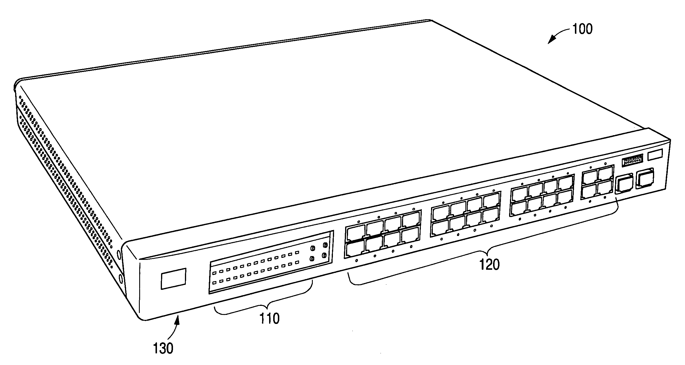
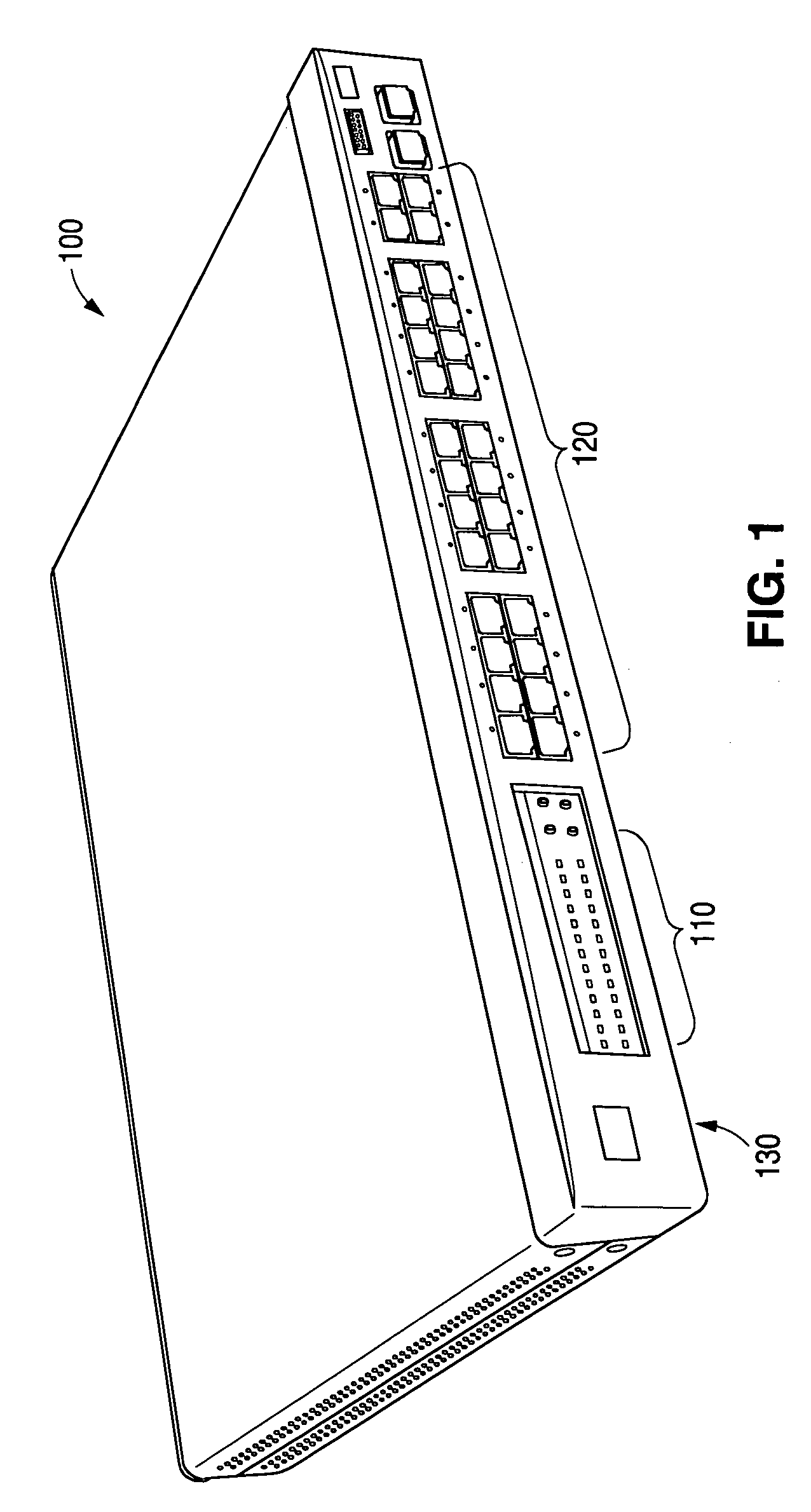
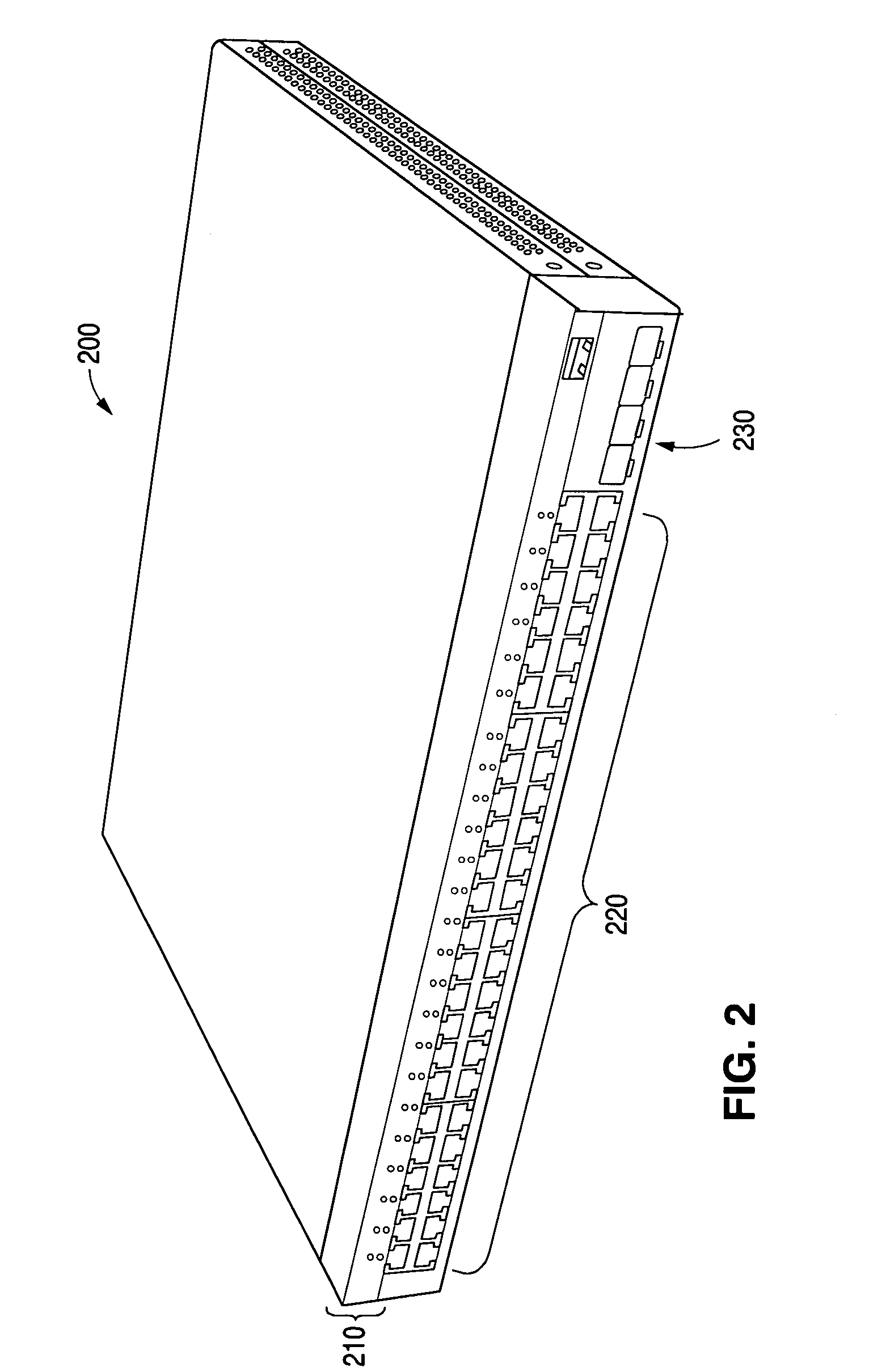
[0016]Referring now to the drawings wherein the showings are for purposes of illustrating embodiments of the present invention only, and not for purposes of limiting the same, FIGS. 1 and 2 provide perspective views of network devices 100 and 200 with status indicators in accordance with an embodiment of the present invention. As also shown in FIGS. 1 and 2, each of network devices 100 and 200 may be implemented with rack-mountable hardware to facilitate convenient stacking of one or more of each of network devices 100 and 200 in particular applications.

[0017]Referring to FIG. 1, network device 100 includes a plurality of status indicators implemented as light emitting diodes (LEDs) 110 visible from a front panel 130. Network device 100 further includes a plurality of ports 120 which may be implemented, for example, as Ethernet ports or other input / output ports known in the art.

[0018]Similarly, in FIG. 2, network device 200 includes a plurality of status indicators implemented as LE...


PUM


Abstract

Systems and methods are provided to facilitate the display of status information associated with a network device using a plurality of multi-function status indicators, such as light emitting diodes (LEDs). In one implementation, a network device includes a plurality of user-viewable status indicators adapted to display status information associated with the network device. The network device further includes a processor adapted to detect a plurality of event conditions at the network device. A logic circuit of the network device is adapted to determine first and second sets status information to be displayed by the status indicators. A control circuit of the network device is adapted to provide the status indicators with display states associated with the first and second sets of status information without requiring user interaction with the network device. The event conditions may be multiplexed to identify associations between the event conditions and the display states.

Description

BACKGROUND[0001]1. Field of the Invention[0002]The present invention generally relates to networking and more particularly to the monitoring of networked systems.[0003]2. Related Art[0004]Modern computing systems often include various network devices to facilitate network-based communications. For example, network devices such as switches and routers may be interconnected with each other and various networks to support such communications.[0005]Individual network devices may include display panels to provide status information that may be monitored by a user. Frequently, these display panels are implemented with light emitting diodes (LEDs) configured to display the status of particular parameters of the device or the network system. For example, a first set of LEDs may be provided to indicate the operational status of various ports of the network device, and a second set of LEDs may be provided to indicate various system-related information.[0006]Frequently, such network devices ar...

Claims


Application Information

Patent Timeline
Patent Type & Authority Patents(United States)
IPC IPC(8): G08B21/00
CPCH04L41/0681H04L43/0817H04L41/22
Inventor HUANG, KUNG-SHIUHLEE, HSIU-LINGLIU, TEKAIMAMPOURIAN, RAZMIKNG, KIM-HUIPAN, JAMES K.YAO, SHUCHUAN
Owner CISCO TECH INC
Why Eureka
Try Eureka