
Pontoon crawler track assembly

Active Publication Date: 2009-09-15
REMU
View PDF14 Cites 9 Cited by
  • Summary
  • Abstract
  • Description
  • Claims
  • Application Information

AI Technical Summary

Benefits of technology

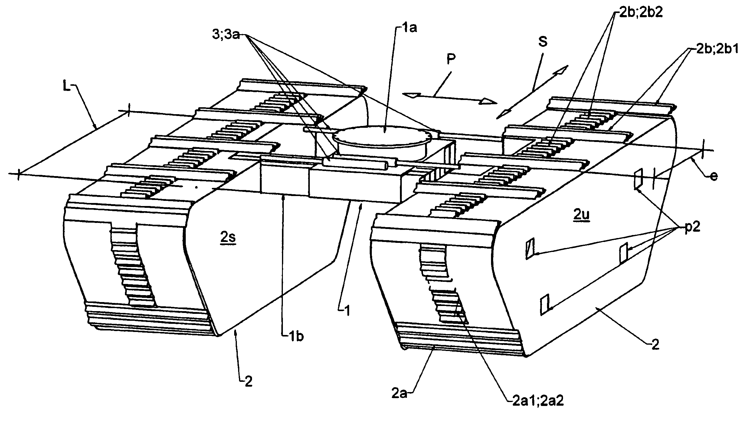
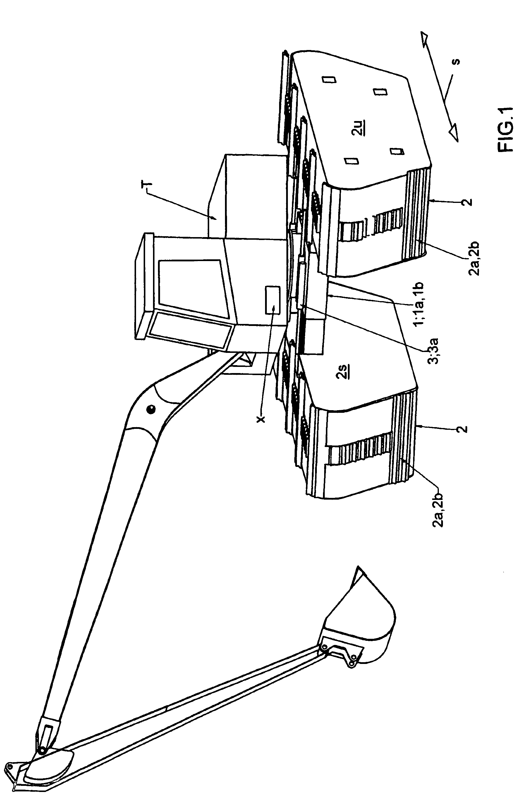
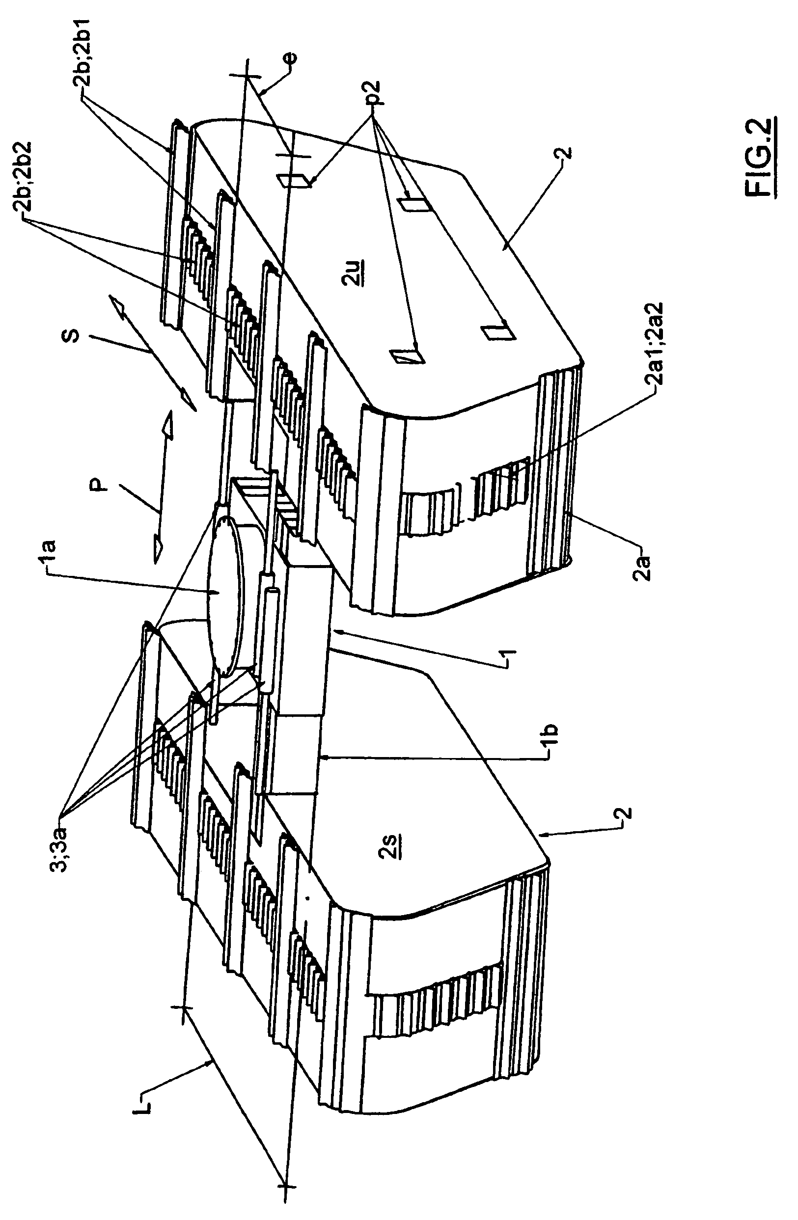
[0007]As the most important advantages of the crawler track assembly according to the invention may be mentioned simplicity and efficiency of its structure, manufacturing and use, whereby with very simple technical solutions it is possible to put together a pontoon crawler track assembly, which can, when being attached to the working machine, first of all be adjusted to a desired optimum operating breadth at any given time and on the other hand be narrowed to its minimum breadth in a way that e.g. in road transportations of the working machine traffic arrangements are not needed, which is the case with extra wide transportations. This is based on the fact that extremely simple structures have been utilized in the pontoon crawler track assembly particularly for the part of the power transmission arrangements moving the crawler track arrangements of the pontoon members so that for their part it is possible to achieve significant cost savings from the point of view of manufacturing. This has been achieved by using in each pontoon member only one power transmission arrangement, being placed essentially at the center of the pontoon member and in which each crawler track part of the crawler track arrangement is attached to the power transmission chain from its middle.
[0008]As an advantageous embodiment, the crawler track arrangement comprises furthermore shorter and longer crawler track parts that are arranged in a way that the mutual distance of the longer crawler track parts from each other in the longitudinal direction is greater than the total length of the mounting frame, which arrangements together with a cavity, existing in the internal side wall of the pontoon member, enable withdrawing of the mounting frame partially inside the pontoon member between the first crawler track parts. In usual crawler track solutions there has been used traditionally two power transmission arrangements, being placed at opposite edges of the crawler track frame, between which the crawler track parts have been fastened, which does not enable withdrawing of the fastening frame inside the pontoon members. On the other hand according to the invention it is also possible to arrange the pontoon members to move simultaneously downwards during the sideward movement by means of the fastening beams, being placed in inclined positions, which enables adjustment of the operating height of the working machine.
[0009]One crucial advantage of the pontoon crawler track assembly according to the invention is thus the adjustment of the operating breadth of the undercarriage, whereby those manual installation stages and extra spare parts, required by e.g. the solution according to U.S. Pat. No. 6,315,622, may be totally avoided thanks to hydraulic cylinders, to be controlled advantageously from the the working machine's cab and operated by means of the operating machine's hydraulic system. The efficiency of the hydraulic cylinders may be optimized particularly thanks to the fact that the forces needed for adjustment may be minimized by lifting the pontoon member, to be adjusted at any given time, e.g. by means of the bucket of the excavator, operating as the working machine, prior to its positioning.

Problems solved by technology

This is why the measures related to a preliminary preparation and transportation of a working machine, being utilized in water, are first of all very laborious to perform and on the other hand get disproportionately expensive particularly due to those special arrangements needed for road transportations.

Method used


Image

  • Pontoon crawler track assembly
  • Pontoon crawler track assembly
  • Pontoon crawler track assembly

Examples


Embodiment Construction

[0019]The invention relates to a pontoon crawler track assembly, which is intended to be used as a crawler-track-driven undercarriage in a working machine T, such as an excavator, a drilling or a piling machine or like, operating particularly in water, which comprises a mounting frame 1 and pontoon members 2. The mounting frame 1 has coupling means 1a to couple the pontoon crawler track assembly with the working machine T and fastening means 1b for attachment of the box-structured, hollow pontoon members 2 at the sides of the mounting frame 1. Each pontoon member 2 is equipped with a crawler track arrangement 2b, which is arranged moveable by way of an internal power transmission arrangement 2a. Furthermore the breadth of the pontoon crawler track assembly is arranged adjustable. With reference e.g. to FIGS. 1, 2 and 5b, the pontoon crawler track assembly has actuators 3 for adjusting its breadth in a way that a working machine equipped with the pontoon crawler track assembly may be...


PUM


Abstract

A pontoon crawler track assembly intended to be used as a crawler-track-driven undercarriage in a working machine. The assembly includes a mounting frame and pontoon members. The mounting frame includes a coupler to couple the pontoon crawler track assembly with the working machine and a fastener for attachment of box-structured, hollow pontoon members at the sides of the mounting frame. Each pontoon member includes a crawler track arrangement, which is arranged moveable by way of an internal power transmission arrangement. The breadth of the pontoon crawler track assembly is adjustable. Actuators adjust a breadth of the assembly in a way that a working machine equipped with the pontoon crawler track assembly may be brought, by changing the distance between its pontoon members with the actuators, operating by auxiliary power, first into a narrowed position particularly and on the other hand into a broadened position.

Description

CROSS-REFERENCE TO RELATED APPLICATIONS[0001]This application claims priority to Finnish patent application 20040436 filed 23 Mar. 2004 and is the national phase under 35 U.S.C. § 371 of PCT / FI2004 / 000764 filed 15 Dec. 2004.FIELD OF THE INVENTION[0002]The invention relates to a pontoon crawler track assembly, which is intended to be used as a crawler-track-driven undercarriage in a working machine, such as an excavator, a drilling or a piling machine or like, operating particularly in water, which comprises a mounting frame and pontoon members. The mounting frame has coupling means to couple the pontoon crawler track assembly with a working machine and fastening means for attachment of the box-structured, hollow pontoon members at the sides of the mounting frame. Each pontoon member is equipped with a crawler track arrangement, which is arranged moveable by way of an internal power transmission arrangement. Furthermore the breadth of the pontoon crawler track assembly is arranged ad...

Claims


Application Information

Patent Timeline
IPC IPC(8): B60F3/00B60FB62D49/06B62D55/084B62D55/10E02F9/02
CPCB60F3/0038B62D49/0678E02F9/024B62D55/10B62D55/084
Inventor KOSKINEN, KALEVI
Owner REMU
Learn More