Coaxial cable connector with gripping ferrule

a technology of coaxial cable and ferrule, which is applied in the direction of relieving strain on wire connection, two-part coupling device, coupling device connection, etc., can solve the problems of unsatisfactory electrical and mechanical connection, large manual force to be applied, and difficulty in preparing the end of a coaxial cable for installation into a connector. achieve the effect of enhancing gripping and sealing and reducing steps

Active Publication Date: 2009-09-15
PPC BROADBAND INC
View PDF243 Cites 81 Cited by
  • Summary
  • Abstract
  • Description
  • Claims
  • Application Information

AI Technical Summary

Benefits of technology

[0010]It is a further object of the present invention to provide a coaxial cable connector which reduces the steps required to prepare an end of a coaxial cable.
[0011]It is still a further object of the present invention to provide a coaxial cable connector having structure to enhance gripping and sealing of a coaxial cable, especially a small diameter coaxial cable.
[0013]In a preferred embodiment, the gripping ferrule preferably includes at least one flexible finger disposed at each opposite end of the ferrule, which deflects radially inward upon insertion of the locking sleeve into the connector body to grip a cable inserted into the connector and to prevent rearward removal of the cable from the connector body. The flexible fingers of the gripping ferrule preferably include a tapered forward end defining a sharp edge to enhance gripping of the cable. The connector body preferably includes an internal ramp portion for deflecting a forward flexible finger of the gripping ferrule radially inward and the locking sleeve preferably includes an internal ramp portion for deflecting a rearward flexible finger of the gripping ferrule radially inward upon insertion of the locking sleeve into the connector body. The gripping ferrule further preferably includes an internally threaded or corrugated inner surface adapted to threadably or otherwise engage an outer surface of a coaxial cable.
[0015]The present invention further involves a method for terminating a coaxial cable in a connector. The method according to the present invention generally includes the steps of inserting an end of a cable into an axially movable locking sleeve disposed within a rearward cable receiving end of a connector body which has a gripping ferrule supported therein and moving the locking sleeve forward to compress opposite ends of the gripping ferrule around the cable at two locations. As a result of the present invention, the time required to prepare the end of a coaxial cable prior to installation on the connector is drastically reduced.

Problems solved by technology

Needless to say, the process of preparing an end of a coaxial cable for installation into a connector requires a modicum of skill and is somewhat time consuming.
A further problem with current coaxial connectors is that in order to properly attach the connector to the coaxial shielded cable, a good deal of manual force must be applied to push the coaxial shielded cable over the barbs of the post.
During conventional installation, the cable can buckle when the post with the barb is pushed between the foil and the braid and create an unsatisfactory electrical and mechanical connection.
Thus, a mistake made in the preparation process may result in a faulty connector installation.
Another problem with current coaxial connectors is that they are often difficult to use with smaller diameter coaxial cables.
In particular, current coaxial connectors often do not adequately grip smaller diameter coaxial shielded cables.
Moreover, sealing the interior of the connector from outside elements also becomes more challenging with smaller diameter cables.

Method used


Image

  • Coaxial cable connector with gripping ferrule
  • Coaxial cable connector with gripping ferrule
  • Coaxial cable connector with gripping ferrule

Examples


Embodiment Construction

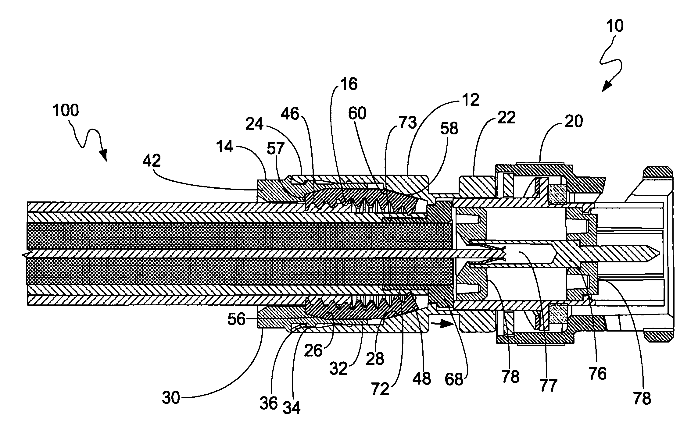
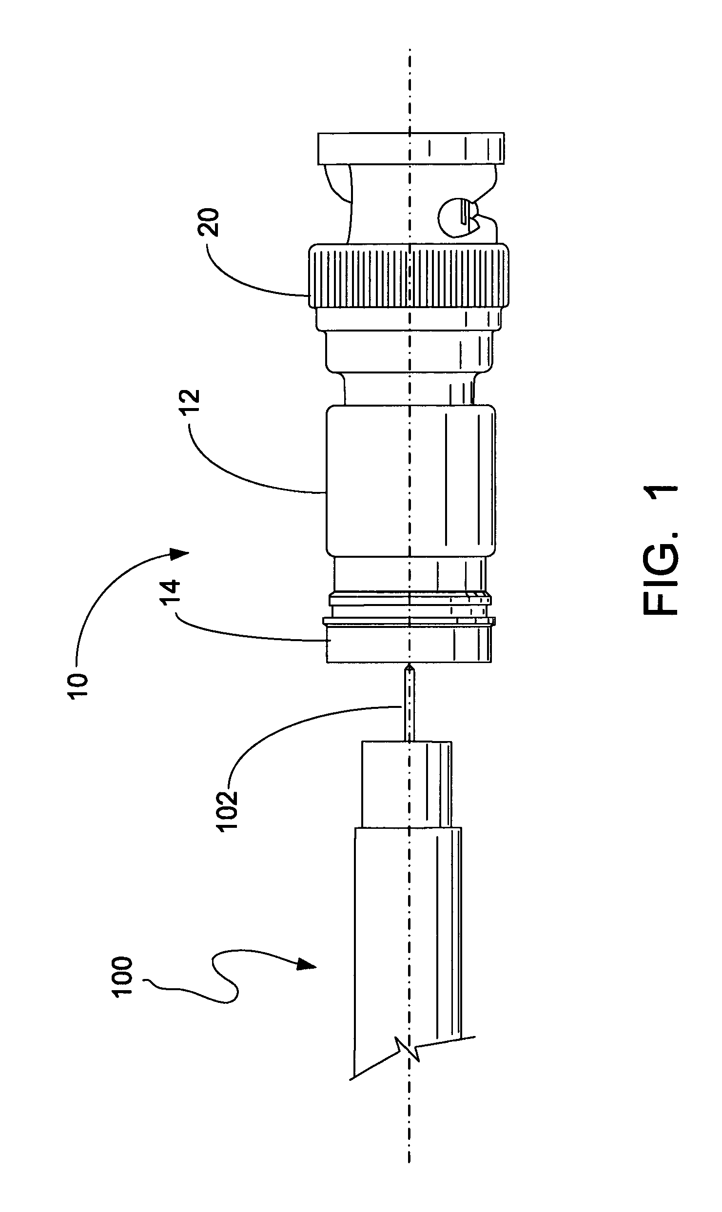
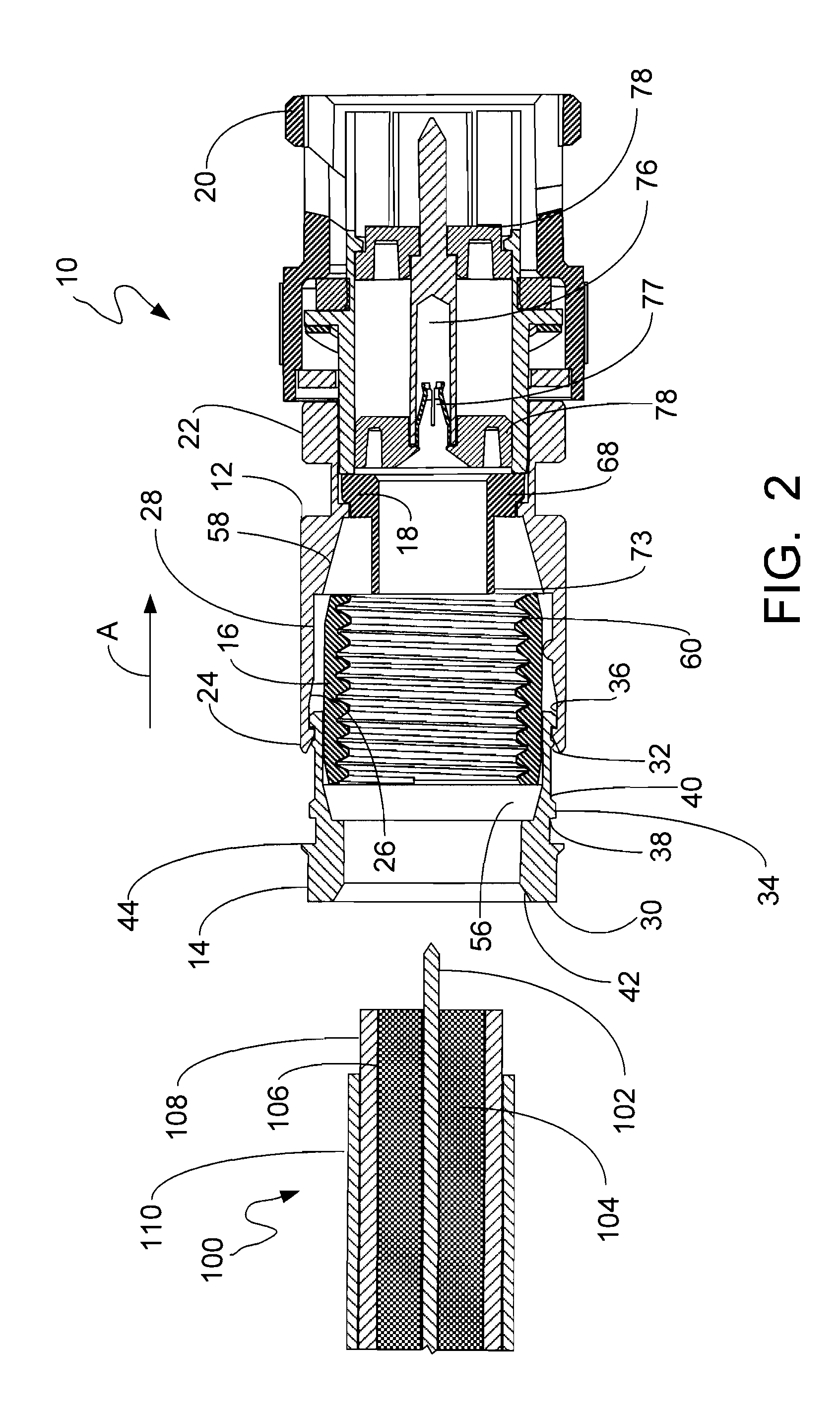
[0025]Referring now to the drawings, the coaxial cable connector 10 of the present invention generally includes a connector body 12, a locking sleeve 14 and a gripping ferrule 16. As will be discussed in further detail below, the connector of the present invention further preferably includes an annular post 18 and a rotatable nut 20. It is however conceivable that the connector body 12 and the post 18 can be integrated into one component and / or another fastening device other than the rotatable nut 20 can be utilized.

[0026]The connector body 12, also called a collar, is an elongate generally cylindrical member, which is preferably made from plastic to minimize cost. Alternatively, the body 12 may be made from metal or the like. The body 12 has a forward end 22 coupled to the post 18 and the nut 20 and an opposite cable receiving end 24 for insertably receiving the locking sleeve 14, as well as a prepared end of a coaxial cable 100 in the forward direction as shown by arrow A. Also di...


PUM


Abstract

A coaxial cable connector includes a connector body having a rearward cable receiving end, a locking sleeve movably coupled within the rearward cable receiving end of the connector body for locking the cable in the connector and a gripping ferrule disposed between the connector body and the locking sleeve. The gripping ferrule includes axially opposite gripping ends which move in a radially inward direction upon compression between the locking sleeve and the connector body to grip the outer surface of the cable.

Description

CROSS-REFERENCE TO RELATED APPLICATIONS[0001]This application claims the benefit of U.S. Provisional Application No. 60 / 923,817, filed on Apr. 17, 2007, which is incorporated by reference herein in its entirety for all purposes.BACKGROUND OF THE INVENTION[0002]The present invention relates generally to connectors for terminating coaxial cable. More particularly, the present invention relates to a coaxial cable connector having structural features to enhance gripping of a coaxial cable and to provide sealing of the interior of the connector from the environment, while minimizing the steps required to prepare the end of a coaxial cable.[0003]It has long been known to use connectors to terminate coaxial cable so as to connect a cable to various electronic devices such as televisions, radios and the like. Prior art coaxial connectors generally include a connector body having an annular collar for accommodating a coaxial cable, an annular nut rotatably coupled to the collar for providing...

Claims


Application Information

Patent Timeline
Patent Type & Authority Patents(United States)
IPC IPC(8): H01R9/05
CPCH01R13/5202H01R13/5816H01R9/0524H01R24/40H01R13/623H01R2103/00H01R13/5804H01R13/59H01R9/05
Inventor MALLOY, ALLEN L.KNAUS, GARYTHOMAS, CHARLES
Owner PPC BROADBAND INC
Why Eureka
Try Eureka