
Synthetic aperture radar systems and methods

a radar and synthetic aperture technology, applied in the field of synthetic aperture radar, can solve the problems of difficult alignment of two separate reference systems of a bistatic sar system, difficult to achieve accurate results, and difficulty in generating quality images in a bistatic sar

Inactive Publication Date: 2009-09-15
THE UNITED STATES OF AMERICA AS REPRESENTED BY THE SECRETARY OF THE NAVY
View PDF12 Cites 17 Cited by
  • Summary
  • Abstract
  • Description
  • Claims
  • Application Information

AI Technical Summary

Problems solved by technology

Unlike monostatic SAR where the illuminator and receiver are co-located, this information is difficult to accurately obtain in bistatic SAR making it difficult to align the two separate reference systems of a bistatic SAR system.
As a result, the generation of quality images in a bistatic SAR is difficult.
This approach increases the complexity of such systems and furthermore, has several inherent difficulties and risks.
For example, maintaining a data link in a real-time operational environment may be difficult due to interfering and jamming signals resulting in an inability to generate a quality image.

Method used


Image

  • Synthetic aperture radar systems and methods
  • Synthetic aperture radar systems and methods
  • Synthetic aperture radar systems and methods

Examples


Embodiment Construction

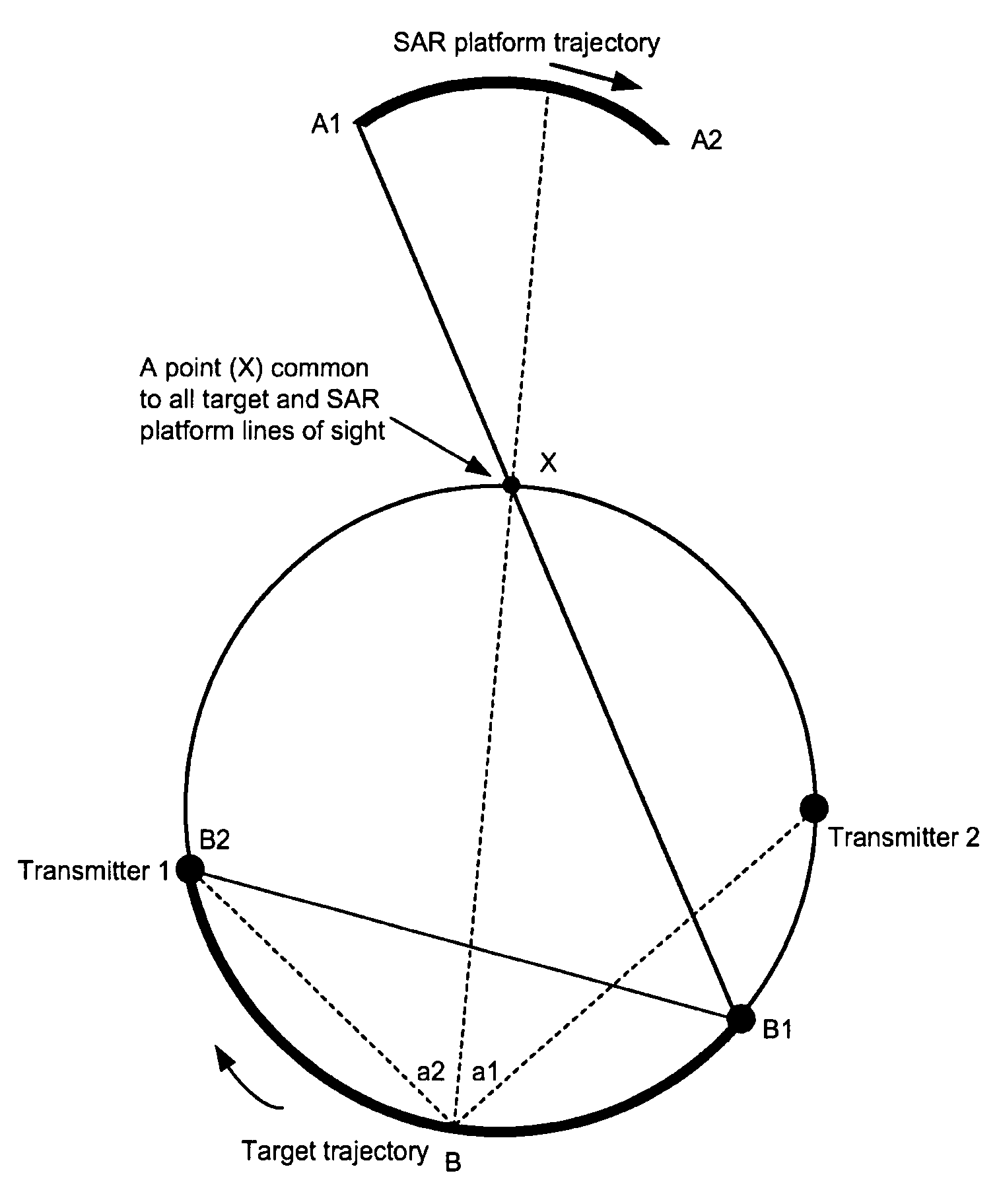
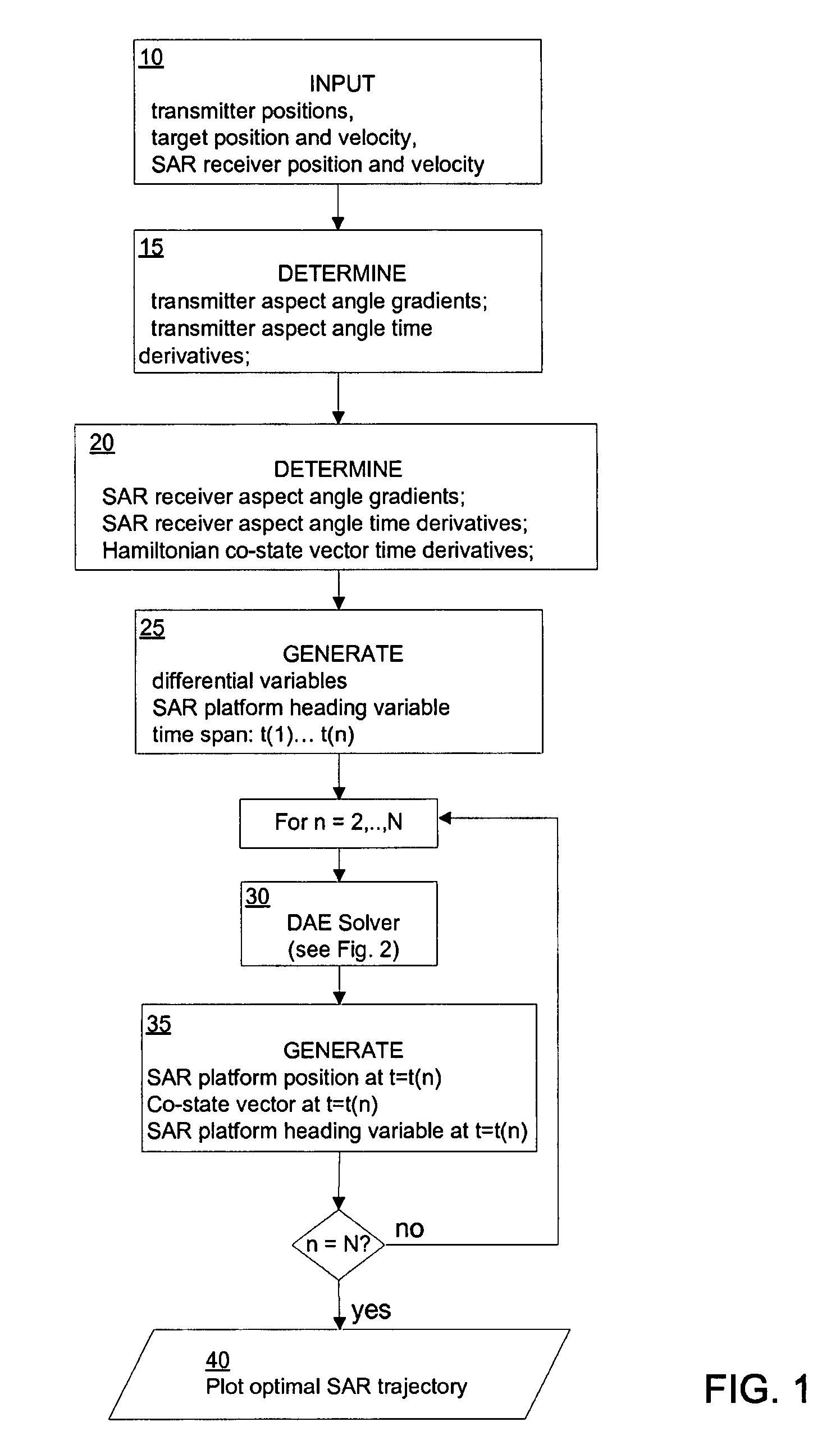
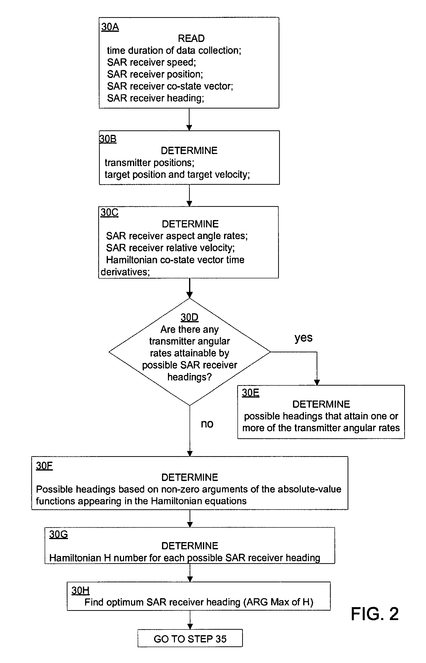
[0012]In the following paragraphs, the Optimal SAR Receiver Path algorithm will be described in detail by way of example with reference to the attached drawings. While the Optimal SAR Receiver Path algorithm is capable of embodiment in many different forms, there is shown in the drawings and will herein be described in detail specific embodiments, with the understanding that the present disclosure is to be considered as an example of the principles of the Optimal SAR Receiver Path algorithm and not intended to limit the Optimal SAR Receiver Path algorithm to the specific embodiments shown and described. That is, throughout this description, the embodiments and examples shown should be considered as exemplars, rather than as limitations on the Optimal SAR Receiver Path algorithm.

[0013]Embodiments of the Optimal SAR Receiver Path algorithm and associated methods (hereafter “OSRP”) employs an algorithm and methods to determine the best trajectory, or equivalently in the case of constan...


PUM


Abstract

A method of determining a radar receiver path, comprising the steps of: obtaining a transmitter position; obtaining a target position and velocity; obtaining a radar receiver position and velocity; determining a transmitter aspect angle gradient, a transmitter aspect angle time derivative and a transmitter co-state vector time derivative; determining a target aspect angle gradient, a target aspect angle time derivative and a target co-state vector time derivative; generating a radar platform heading variable, and a group of differential variables over a defined time span; inputting the group of differential variables into a differential equation solver; receiving a group of possible headings for the radar receiver path; and finding an optimum radar receiver path from the group of possible headings.

Description

FEDERALLY-SPONSORED RESEARCH AND DEVELOPMENT[0001]This invention (Navy Case No. 84482) was developed with funds from the United States Department of the Navy. Licensing inquiries may be directed to Office of Research and Technical Applications, Space and Naval Warfare Systems Center, San Diego, Code 2112, San Diego, Calif. 92152; telephone (619) 553-2778; email: T2@spawar.navy.mil.BACKGROUND OF THE INVENTION[0002]1. Field of the Invention[0003]The present invention relates generally to synthetic aperture radar. More specifically, but without limitation thereto, the present invention relates to optimization of synthetic aperture radar image formation.[0004]2. Description of the Related Art[0005]In monostatic synthetic aperture radar (SAR), the transmitting and receiving antennas share common hardware or a common platform. In bistatic or multistatic SAR, the transmitting and receiving antennas are distinct and at least one component can move along a path independent of the others. In ...

Claims


Application Information

Patent Timeline
Patent Type & Authority Patents(United States)
IPC IPC(8): G01S13/00
CPCG01S13/9035G01S2013/9058G01S13/9029G01S13/904G01S13/9058
Inventor HULBERT, DOUGLAS S.RAMIREZ, AYAX D.RUSSELL, STEPHEN D.SHLMABUKURO, RANDY L.ROBERTS, MARK W.
Owner THE UNITED STATES OF AMERICA AS REPRESENTED BY THE SECRETARY OF THE NAVY
Learn More