Systems and methods for driving a display device and interrupting a feedback

a display device and feedback technology, applied in static indicating devices, solid-state devices, instruments, etc., can solve the problems of large volume production of both excess dissipation both in display devices and display driver circuits, etc., and achieve minimal output node voltage and dissipation. , the effect of extra power dissipation

Active Publication Date: 2009-09-15
KONINKLIJKE PHILIPS ELECTRONICS NV
View PDF7 Cites 12 Cited by
  • Summary
  • Abstract
  • Description
  • Claims
  • Application Information

AI Technical Summary

Benefits of technology

[0010]It is, inter alia, an object of the present invention to provide a display device of the type described in the opening paragraph in which variations in the output node voltages and in dissipation is minimal and especially in which extra power dissipation due to an open driver output node is prevented as much as possible. To this end in a display device according to the invention elements the display driver device comprises means for monitoring output voltages of the display driver device ( e.g. for signaling the value of an output voltage to reach a threshold voltage).

Problems solved by technology

A problem however arises in large volume production of both display devices and display driver circuits, since the number of outputs of the driver circuit may be larger than the number of columns to be provided with driving current.
This leads to excess dissipation both in the display device and display driver circuit.

Method used


Image

  • Systems and methods for driving a display device and interrupting a feedback
  • Systems and methods for driving a display device and interrupting a feedback
  • Systems and methods for driving a display device and interrupting a feedback

Examples


Embodiment Construction

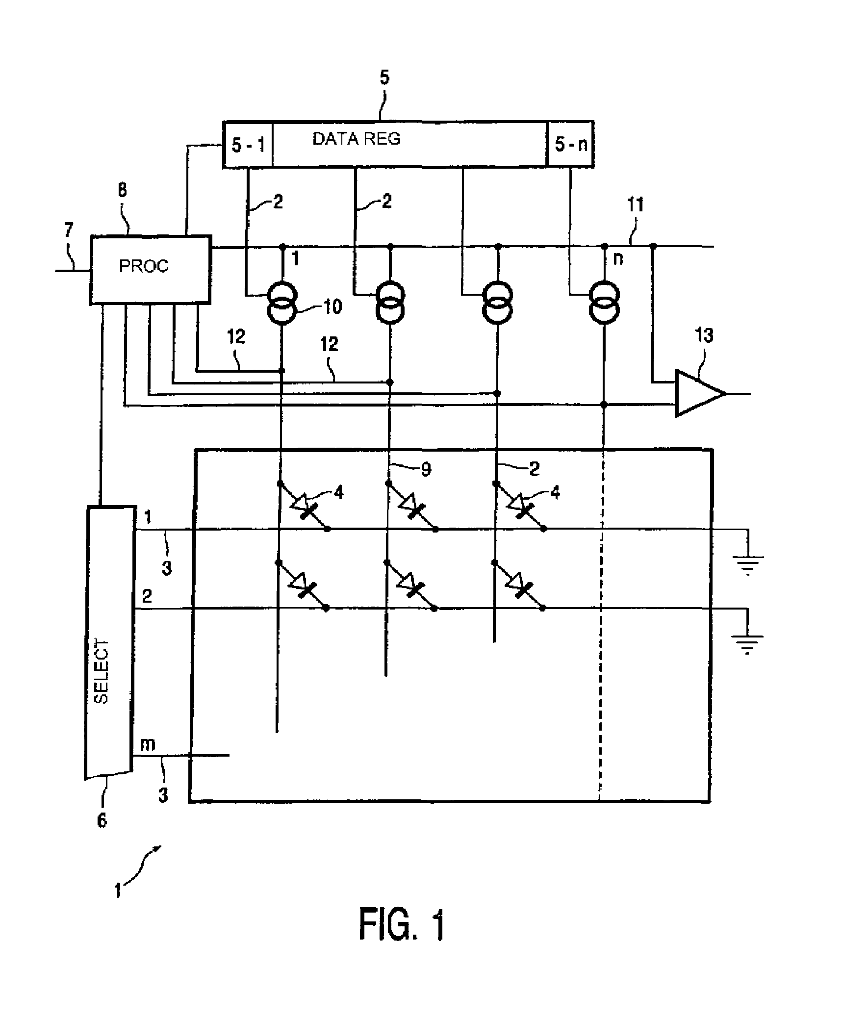
[0020]FIG. 1 shows diagrammatically an equivalent circuit diagram of a part of a display device 1 according to the invention. This display device comprises a matrix of (P) LEDs or (O) LEDs 4 with m rows (1, 2, . . . , m) and n columns (1, 2, . . . , n). This device further comprises a row selection circuit 6 and a data register 5. Externally presented information 7, for example, a video signal, is processed in a processing unit 8 which, dependent on the information to be displayed, charges the separate parts 5-1, . . . , 5-n of the data register 5 via lines 9.

[0021]The selection of a row takes place by means of the row selection circuit 6 via the lines 3, in this example by providing them with the required selection voltage (passive addressing).

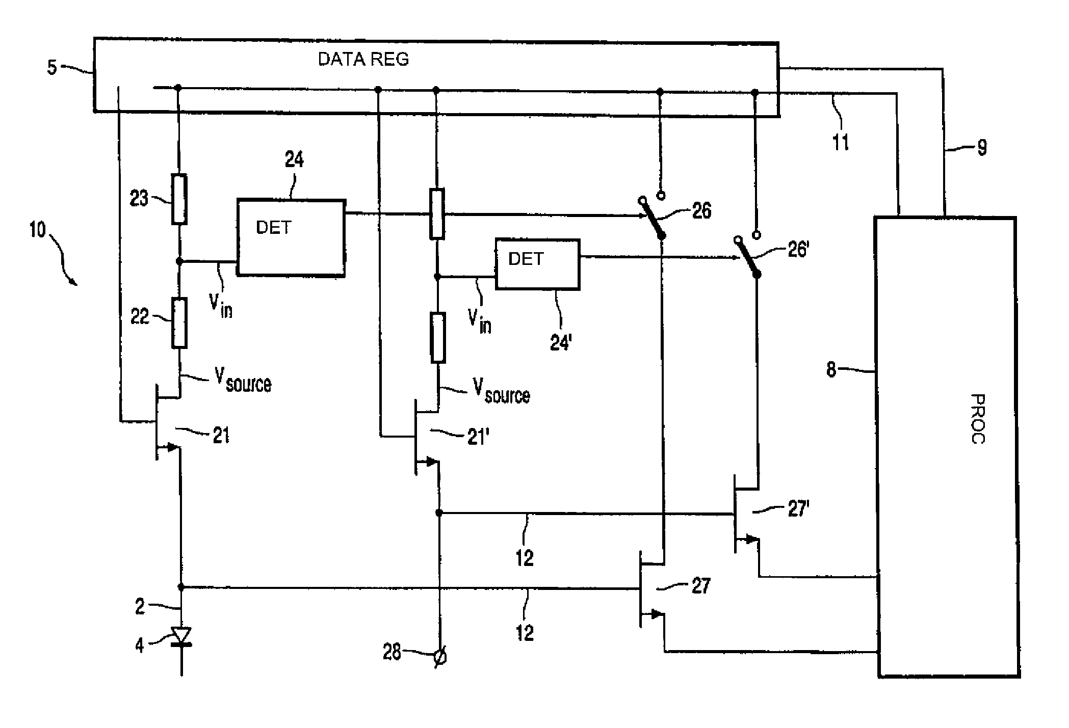
[0022]Writing data takes place in that, during selection, a current source 10, which may be considered to be an ideal current source, is switched on by means of the data register 5, for example via (not shown) switches. The value of the curre...


PUM


Abstract

In a driver for a luminescent display the operating voltage of a driver circuit is monitored to prevent extra dissipation due to open output connections (28) of the driver circuit. The monitoring is also used for minimizing power dissipation.

Description

[0001]This application is a 371 PCT / IB03 / 03280 Jul. 18, 2003.BACKGROUND INVENTION[0002]The invention relates to a display device comprising at least one picture element and a display driver device comprising a driving transistor to be connected in series with the picture element.[0003]Such display devices are increasingly based on electroluminescent semiconducting organic materials, also known as light emitting diodes (polyLEDs or OLEDs). The display devices may either luminesce via segmented pixels (or fixed patterns) but also display by means of a matrix pattern is possible. The adjustment of the diode current generally determines the intensity of the light to be emitted by the pixels.[0004]Suitable fields of application of the display devices are, for example, mobile telephones, organizers, etc.DESCRIPTION OF PRIOR ART[0005]A display device of the type described in the opening paragraph is described in U.S. Pat. No. 6,014,119. In said document, the current through a LED is adjust...

Claims


Application Information

Patent Timeline
Patent Type & Authority Patents(United States)
IPC IPC(8): G09G3/32H01L51/50G09G3/20G09G3/30
CPCG09G3/3216G09G3/3283G09G3/3241G09G2330/04G09G2320/0233G09G2330/021G09G3/20G09G3/30G09G3/32
Inventor SEMPEL, ADRIANUS
Owner KONINKLIJKE PHILIPS ELECTRONICS NV
Why Eureka
Try Eureka