Capacitive coordinate detection device

a detection device and capacitive technology, applied in the direction of static indicating devices, contact mechanisms, instruments, etc., can solve the problems of inability to detect the coordinate position correctly, the display sheet b>7/b> is likely to become dark, and the production cost is likely to ris

Inactive Publication Date: 2009-09-15
ALPS ALPINE CO LTD
View PDF7 Cites 53 Cited by
  • Summary
  • Abstract
  • Description
  • Claims
  • Application Information

AI Technical Summary

Benefits of technology

[0017]The present invention has been finalized in view of the drawbacks inherent in the conventional apparatus, and it is an object of the present invention to provide a capacitive coordinate detection device in which coordinate positions can be correctly detected even in the case where detours for detouring holes in a substrate must be inevitably formed in X electrodes and Y electrodes that detect the coordinate positions.
[0018]Furthermore, it is another object of the present invention to provide a capacitive coordinate detection device in which coordinate positions can be correctly detected even though leading lines are densely disposed in the vicinity of X electrodes or Y electrodes disposed outside.
[0022]Preferably, when a capacitance between the reference common electrode and the first detection electrode is set to CR and a capacitance between the reference common electrode and the second detection electrode is set to CL, a pattern of each of the electrodes is set such that a composite capacitance between the capacitance CR and the capacitance CL can be kept constant in such a manner that one of the two capacitances compensates for an increase or a decrease of the other of the two capacitances.
[0028]In the present invention, although leading lines are densely disposed in the vicinity of Y detection electrodes or X detection electrodes disposed outside, or common electrodes that form a capacitance between the detection electrodes disposed outside cannot be disposed opposite to each other due to the formation of holes, the shortage of a capacitance can be supplemented. It is thus possible to correctly detect coordinate positions.

Problems solved by technology

Thus, there is a problem in that the display sheet 7 is likely to become dark.
There is, however, a problem in that the production cost is likely to rise because ITO is expensive.
Due to this, there is a problem in that a coordinate position cannot be detected correctly because a capacitance between the respective lines is greatly different.
However, if the wiring patterns are densely disposed in the vicinity of the X electrodes or the Y electrodes disposed outside, a capacitance for the X electrodes or the Y electrodes becomes unstable.
Accordingly, there is also a problem in that it is difficult to correctly detect coordinate positions.

Method used


Image

  • Capacitive coordinate detection device
  • Capacitive coordinate detection device
  • Capacitive coordinate detection device

Examples


first embodiment

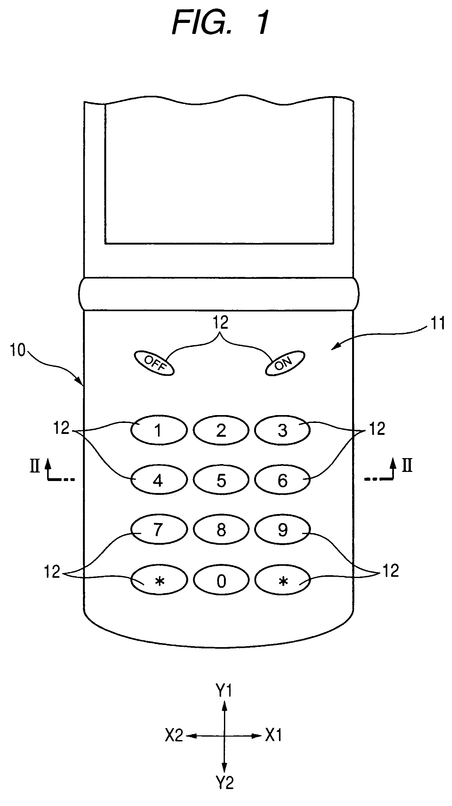
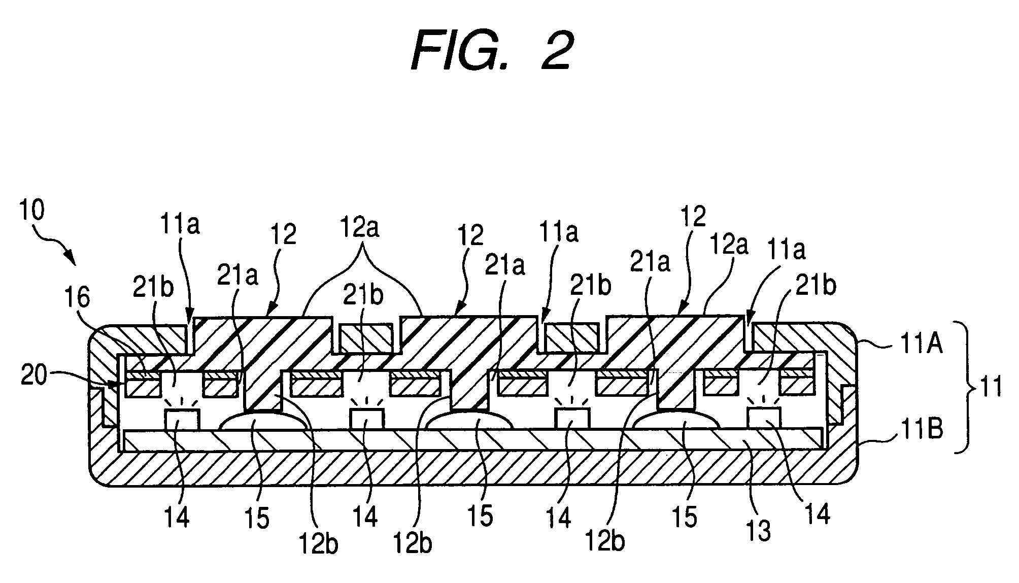
[0044]FIG. 1 is a plan view of a cellular phone as an information terminal apparatus in which a coordinate detection device according to the present invention is mounted. FIG. 2 is a cross-sectional view of the cellular phone taken along the line II-II of FIG. 1. FIG. 3 is a plan view of a base sheet and electrode patterns constituting a coordinate detection device according to the present invention. FIG. 4 is a plan view of X detection electrodes and common electrodes formed on one surface of the base sheet of FIG. 3. FIG. 5 is a plan view of a case in which the common electrode formed on one surface of the base sheet of FIG. 3 and the Y detection electrodes formed on the other surface of the base sheet of FIG. 3 are viewed from the same direction as FIG. 4. Further, in FIGS. 3 to 5, only insertion holes 21a through which stems 12b pass are shown, but passage holes 21b through which light is transmitted are omitted.

[0045]FIG. 1 shows an operation unit 11 of a cellular phone 10 gene...

second embodiment

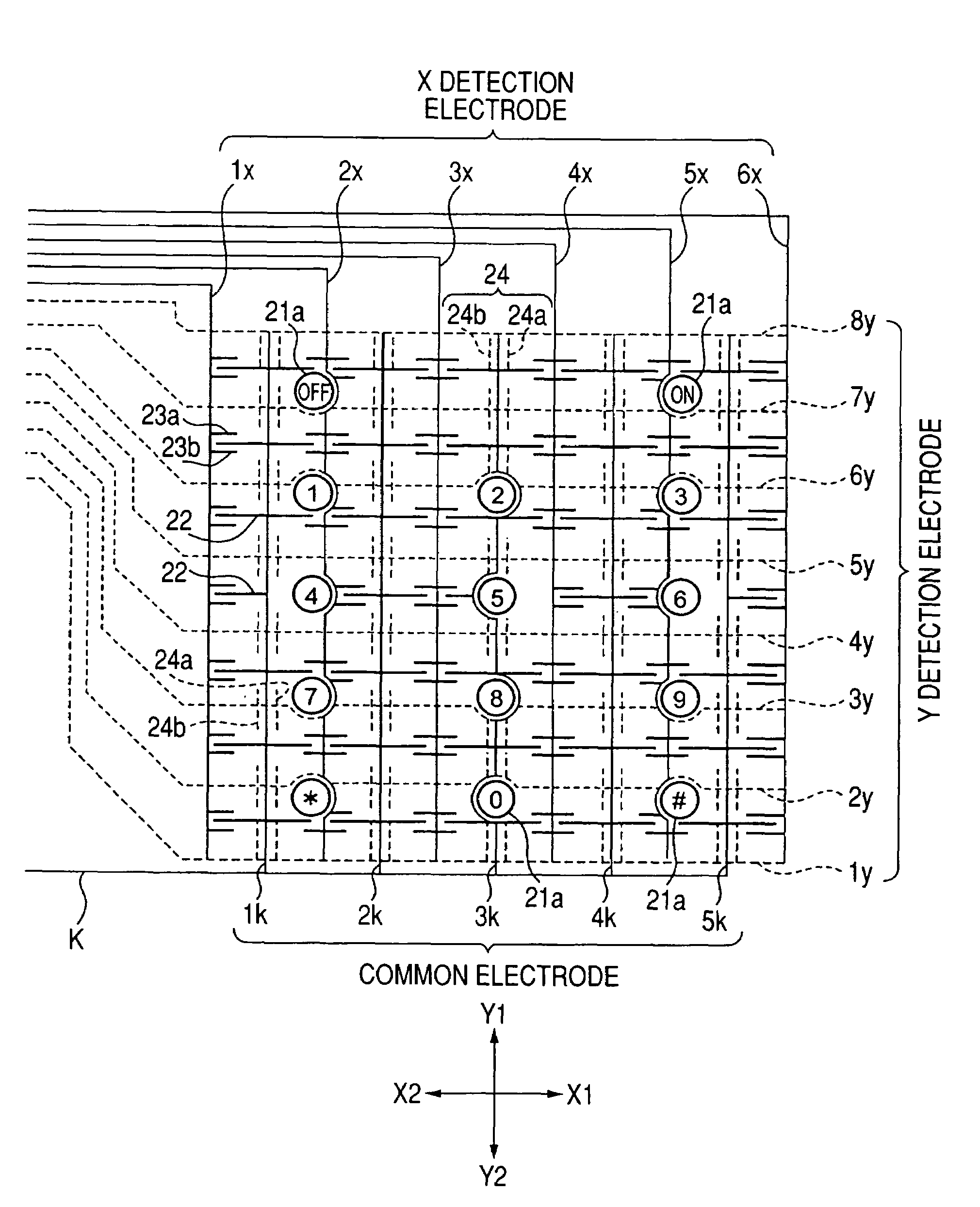
[0104]FIG. 9 is a plan view of a base sheet 21 and electrode patterns constituting the coordinate detection device according to the present invention. FIG. 10A is a partial enlarged plan view of the coordinate detection device shown in FIG. 9, and FIG. 10D is a cross-sectional view of the device shown in FIG. 10A. At this time, the coordinate detection device 40 is fixed on the bottom surface of the keymat by means of the adhesive 16.

[0105]Further, in FIG. 9, solid lines having no hatching indicate X detection electrodes 1x, 2x, 3x, 4x, 5x and 6x formed on one surface of the base sheet 21, and solid lines having hatching indicate common electrodes 1k, 2k, 3k, 4k and 5k formed on one surface of the base sheet 21. Furthermore, dotted lines indicate Y detection electrodes 1y, 2y, 3y, 4y, 5y, 6y, 7y and 8y formed on the other surface of the base sheet 21. Further, squares of a bold line indicate insertion holes 21a and rectangles of a bold line indicate passage holes 21b. Circular holes...


PUM


Abstract

A composite capacitance between a common electrode and an X detection electrode having a plurality of detours is small, whereas lengths of parallel electrodes of the X detection electrode are set to have large values. A comprehensive composite capacitance is set to be constant by increasing a composite capacitance between the common electrode and the X detection electrode. For this reason, although the detours are formed in the electrode patterns, a coordinate position can be detected with high accuracy.

Description

[0001]This application claims the benefit of priority to Japanese Patent Application No. 2004-294526, filed on Oct. 7, 2004, herein incorporated by reference.BACKGROUND OF THE INVENTION[0002]1. Field of the Invention[0003]The present invention relates to a coordinate detection device mounted in an information terminal apparatus, such as cellular phones or PDAs. More particularly, the present invention relates to a capacitive coordinate detection device in which a plurality of X electrodes and a plurality of Y electrodes are arranged to cross each other at both sides of a base sheet.[0004]2. Description of the Related Art[0005]Japanese Unexamined Patent Application Publication No. 2002-123363 described below is an example of the related art.[0006]In Japanese Unexamined Patent Application Publication No. 2002-123363, a switch element 11 in which a reversion plate 10 is disposed is provided at a lower side, and a capacitive coordinate detection device (a flat panel input device 4) is p...

Claims


Application Information

Patent Timeline
Patent Type & Authority Patents(United States)
IPC IPC(8): G09G5/00
CPCG06F3/0213G06F3/044H01H13/807H01H2003/0293H01H2205/016H01H2239/006H01H2219/062H01H2221/07H01H2225/002H01H2225/03H01H2215/036G06F3/0446
Inventor SATO, TADAMITSU
Owner ALPS ALPINE CO LTD
Why Eureka
Try Eureka