AI technical title is built by Patsnap AI team. It summarizes the technical point description of the patent document.
a technology of clinching nuts and nut shells, which is applied in the direction of threaded fasteners, screwdrivers, manufacturing tools, etc., can solve the problems of difficult deformation of heavy metal panels downwardly into the groove and beneath, inner and outer side walls, and difficult deformation of heavy metal panels exceeding about 1.5 mm, so as to achieve adequate pull-out resistance, increase the thickness of the panel, and effective deformation
Inactive Publication Date: 2009-09-22
PENN AUTOMOTIVE INC
View PDF76 Cites 19 Cited by
Summary
Abstract
Description
Claims
Application Information
AI Technical Summary
This helps you quickly interpret patents by identifying the three key elements:
Problems solved by technology
Method used
Benefits of technology
Benefits of technology
[0007]The self-attaching fastener of the present invention solves the problem associated with prior art configurations, in particular, for use in heavy metal and in a restricted area requiring a fastener with a small foot print. The pilot height of the inventive fastener is adjustable to account for increased panel thicknesses. Furthermore, the absence of an outer annular wall enables the die button to more effectively deform a heavy metal panel radially inwardly beneath the undercut of the pilot portion of the inventive fastener. The deformation of the heavy metal panel beneath the undercut of the pilot portion has proven to provide adequate pull-out resistance not provided by thin metal panels without an outer annular wall. Additionally, the elimination of the outer annular wall significantly decreases the foot print of the inventive pierce fastener enabling the use of the pierce fastener in confined areas that previously required the use of a weld nut or other alternative fastener.
Problems solved by technology
However, a groove of this type has proven less effective for heavy metal panels exceeding about 1.5 mm.
Specifically, it has proven difficult to deform the heavy metal panel downwardly into the groove and beneath the undercuts associated with the inclined inner and outer side walls.
Further difficulties arise when it is necessary to install a self-piercing or clinching fastener into a panel having a restricted area such as, for example, an automotive seat frame or the like.
It has become evident that there is a heart felt need for self-piercing or clinching fastener which can be used in a heavy metal panel without requiring a large foot print while not sacrificing desirable retention or torque resistant characteristics.
Method used
Image
Click on the blue label to locate the original text in one second.
Reading with bidirectional positioning of images and text.
Examples
Embodiment Construction
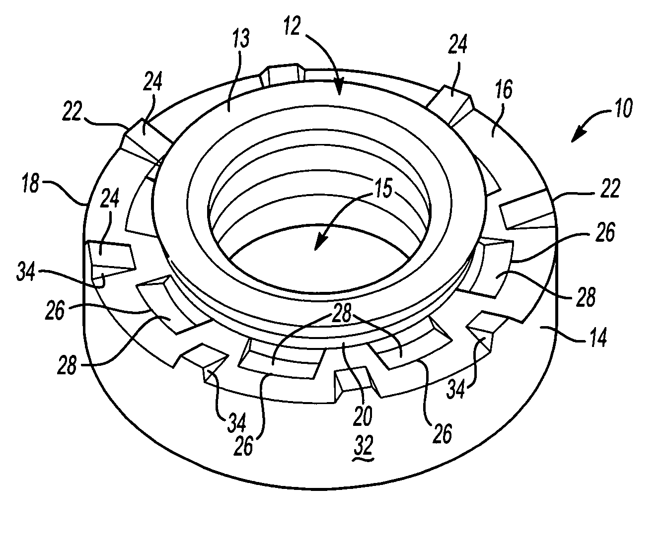
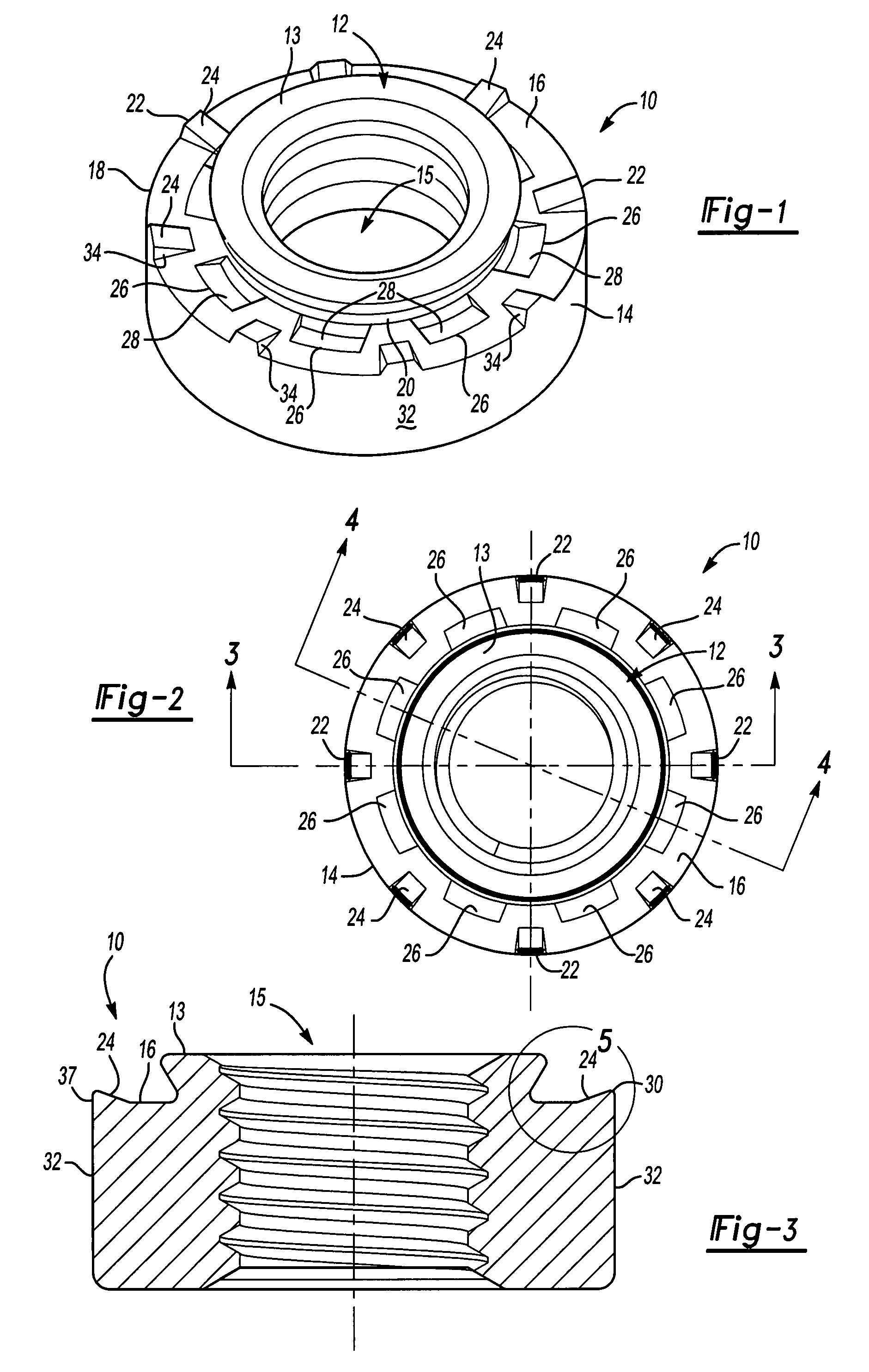
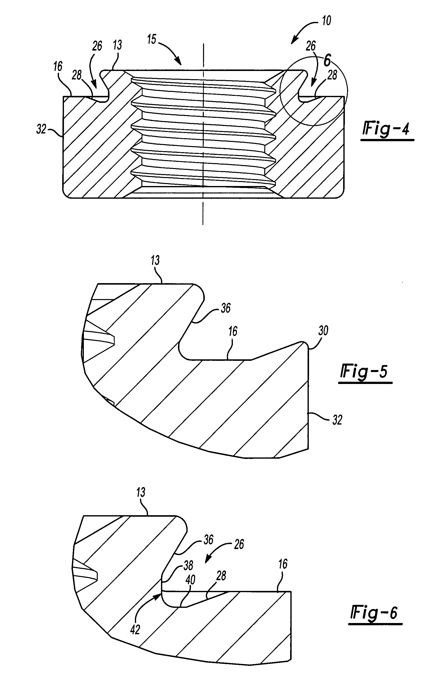
[0018]A self-attaching fastener of the present invention is generally shown in FIG. 1 at 10. The fastener 10 represented in FIG. 1 may be used as a self-piercing or self-clinching fastener as the end user may desire. In the event that the fastener 10 is used as a self-piercing fastener, a pilot portion 12 pierces an aperture through a metal panel (not shown) as is known to those of skill in the art. Alternatively, if the fastener 10 is used merely as a self-clinching fastener, the pilot portion 12 is inserted through a pre-pierced hole as is also known to those of skill in the art.
[0019]An annular flange 14 surrounds the central pilot portion 12 and has a generally planar end face 16 defining a peripheral edge 18. The central pilot portion 12 terminates at a pilot end 113 that is also generally planar and substantially parallel to the generally planar end face 16. The pilot portion 12 defines a bore 15 that is threaded or un-threaded depending upon the desired application. The perip...
PUM
Abstract
A self-attaching fastener includes a pilot portion having an outer side wall and is surrounded by an annular flange. The annular flange includes a planar end face defining a peripheral edge with a diameter greater than a diameter of said outer side wall of the pilot portion. The end face includes a plurality of first circumferentially spaced anti-rotation elements each having a planar top face spaced above the planar end face of the annular flange and a second plurality of second circumferentially spaced anti-rotation elements each having a planar top face spaced below the planar end face of the annular flange. Each of the first and second anti-rotation elements extend from about one of the peripheral edge of the annular flange and the outer side wall to a location spaced from the other of the peripheral edge of the flange portion and the outer side wall of the pilot portion.
Description
RELATED APPLICATION[0001]This application claims priority to Provisional Application Ser. No. 60 / 745,965 filed Apr. 28, 2006, and to U.S. patent application Ser. No. 11 / 189,685 filed Jul. 26, 2005, which is a divisional of Ser. No. 10 / 439,526 filed May 16, 2003, now U.S. Pat. No. 6,994,500 (issued Feb. 7, 2006), which is a continuation-in-part of Ser. No. 10 / 232,335 filed Aug. 30, 2002, now U.S. Pat. No. 6,851,904 (issued Feb. 8, 2005).FIELD OF THE INVENTION[0002]This invention relates to self-attaching fasteners, particularly including pierce and clinch nuts and studs, which may be formed by conventional cold header techniques. More specifically, this invention relates to self-piercing and clinching nuts and studs that provide improved retention and resistance to rotation when installed into a panel.BACKGROUND OF THE INVENTION[0003]Self-attaching female fasteners, including pierce and clinch nuts, formed by cold header techniques and secondary press operations generally include a c...
Claims
Application Information
Patent Timeline
Application Date:The date an application was filed.
Publication Date:The date a patent or application was officially published.
First Publication Date:The earliest publication date of a patent with the same application number.
Issue Date:Publication date of the patent grant document.
PCT Entry Date:The Entry date of PCT National Phase.
Estimated Expiry Date:The statutory expiry date of a patent right according to the Patent Law, and it is the longest term of protection that the patent right can achieve without the termination of the patent right due to other reasons(Term extension factor has been taken into account ).
Invalid Date:Actual expiry date is based on effective date or publication date of legal transaction data of invalid patent.

