Knob assembly

a technology of rotary knobs and knobs, applied in the direction of electric switches, contact mechanisms, electrical equipment, etc., can solve the problems of reducing the service life of the user, affecting the reliability of the user, so as to reduce or eliminate the switching of the rotary knobs

Active Publication Date: 2009-09-22
HARRIS GLOBAL COMMUNICATIONS INC
View PDF4 Cites 23 Cited by
  • Summary
  • Abstract
  • Description
  • Claims
  • Application Information

AI Technical Summary

Benefits of technology

[0005]Embodiments of the present invention provide improved knob assemblies for reducing or eliminating switching of a rotary knob to one or more non-preferred states during a mode of operation by requiring a user to exert a force on the knob prior to allowing rotation. In a first embodiment, a switch assembly is provided. The switch assembly includes a rota

Problems solved by technology

Although the operation of many rotary switch designs is straightforward, many permit the transceiver to be inadvertently turned off by a user turning the rotary switch too far.
In some devices, such as satellite transceivers, a reboot period of significant length is required, delaying resumption of communications.
Although some designs of satellite transceivers prevent resetting in the reset position by requiring actuation of a second button, the user may still inadvertently reset the satellite transceiver.
However, the stem may still be inadvertently pushe

Method used


Image

  • Knob assembly
  • Knob assembly
  • Knob assembly

Examples


Embodiment Construction

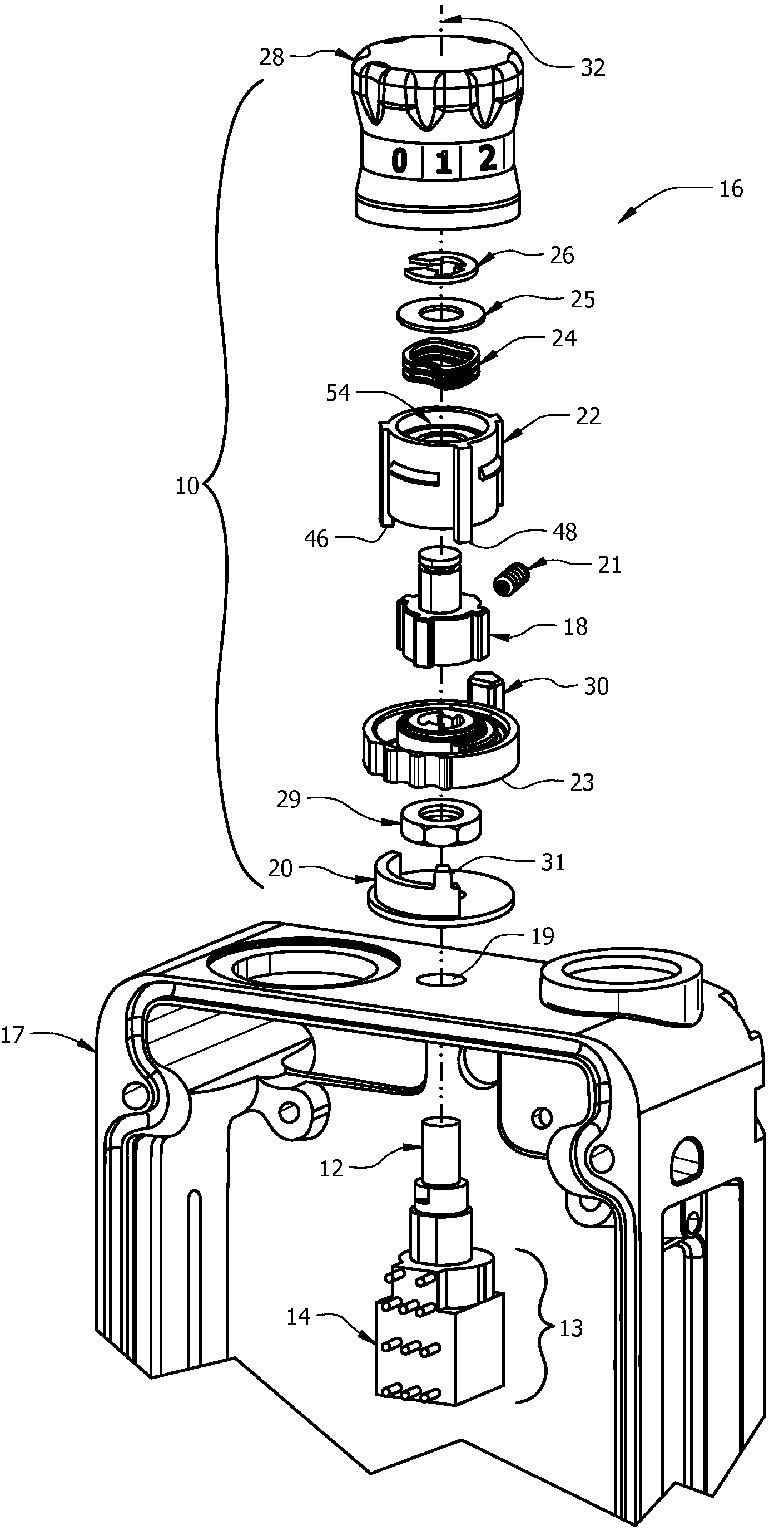
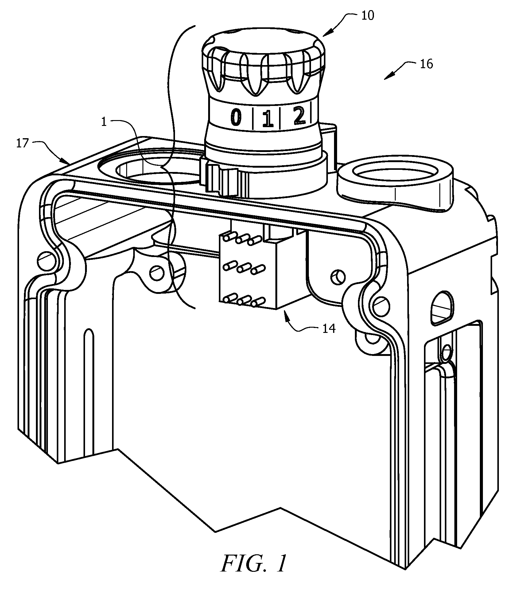
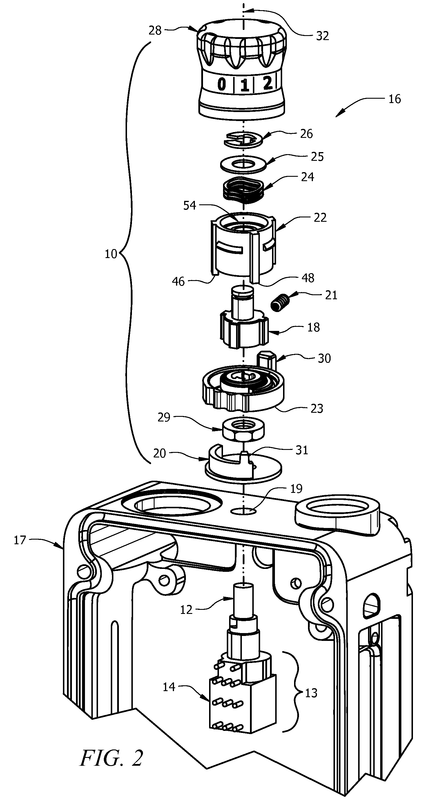
[0026]Embodiments of the present invention of the provide improved knob assemblies for reducing or eliminating switching of a rotary knob to one or more non-preferred states during a mode of operation by requiring a user to exert a force on the knob prior to allowing rotation. In particular, the various embodiments of the present invention provide an improved knob assembly, in which the pull-to-turn functionality is incorporated in the knob assembly, for use with a rotary switch. The various embodiments of the present invention also utilize a stop member-based design, as opposed to existing groove-based designs, which are less susceptible to seizing or otherwise malfunction due to dirt, grit or sand.

[0027]Therefore, the various embodiments of the present invention provide an upper stop member and stop-based knob assembly that can be used with existing rotary switches. Consequently, the amount of interior space required inside a radio as compared to conventional push- or pull-to-turn...


PUM


Abstract

A switch assembly (1) includes a rotary electrical switch body (13) having a plurality of switch positions, a switch stem (12) extending along a first axis (32) and having a first and second ends, the first end engaging the rotary switch (14) for alternating the rotary switch body between the plurality of switch positions responsive to rotation of the switch stem about the first axis, and a knob assembly (10). The knob assembly includes a knob core contacting the second end of the switch stem, a knob collar (22) contacting the knob core and adapted for rotating the knob core and the switch stem about the first axis, where the knob collar includes a first upper stop member (46), and a stop cam (20) having a fixed position relative to the switch stem and disposed between the knob core and the rotary switch, where the stop cam includes a lower stop member (31) having a feature for engaging the first upper stop member when the first upper stop member and the lower stop member are disposed along a common path. In the switch assembly, the first upper stop member travels in a circumferential path normal to the first axis responsive to the knob collar rotating the knob core and the switch stem, where the knob collar is displaceable along the first axis between first and second axial positions, where the lower stop member is in the circumferential path when the knob collar is in the first axial position, and where the lower stop member is removed from the circumferential path when the knob collar is in the second axial position.

Description

FIELD OF THE INVENTION[0001]The present invention is directed to the field of electric switches, and more particularly to switch assemblies for electrical devices.BACKGROUND OF THE INVENTION[0002]Many communications devices, such as radios, typically include a rotary switch which is movable to a number of positions. In a rotary switch for a handheld satellite transceiver and other portable communications devices, these positions typically include “off,”“channels 1-5” (or more), “scan,”“front panel,” and, “Z-all” or “reset.” Generally, the reset position resets the transceiver by clearing all encryption cipher keys inputted by a user. The front panel position is typically used for allowing the channels and modes of operation to be selected using the key pad on the front panel of the transceiver.[0003]Although the operation of many rotary switch designs is straightforward, many permit the transceiver to be inadvertently turned off by a user turning the rotary switch too far. In such a...

Claims


Application Information

Patent Timeline
IPC IPC(8): H01H19/00H01H19/14H01H21/00H01H3/08
CPCH01H19/14H01H3/20H01H3/10H01H19/11
Inventor VANDERWEGE, MICHAELDURAN, JOSE RICARDOBARTHOLOMEW, SCOTT
Owner HARRIS GLOBAL COMMUNICATIONS INC
Why Eureka
Try Eureka